HP Pavilion 10-n100 Maintenance and Service Guide - Page 52
Keyboard base
 |
View all HP Pavilion 10-n100 manuals
Add to My Manuals
Save this manual to your list of manuals |
Page 52 highlights
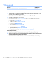
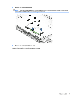
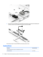
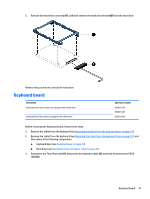
2. Remove the two screws (1) that secures the POGO (10-pin) docking connector board to the display panel assembly, and then remove the POGO (10-pin) docking connector board (2). Reverse this procedure to install the POGO (10-pin) docking connector board. Keyboard base Description Top cover with keyboard for products not equipped with a hard drive In Turbo Silver finish Spare part number 814718-001 44 Chapter 5 Removal and replacement procedures for Authorized Service Provider parts
-
 1
1 -
2
-
3
-
4
-
5
-
6
-
7
-
8
-
9
-
10
-
11
-
12
-
13
-
14
-
15
-
16
-
17
-
18
-
19
-
20
-
21
-
22
-
23
-
24
-
25
-
26
-
27
-
28
-
29
-
30
-
31
-
32
-
33
-
34
-
35
-
36
-
37
-
38
-
39
-
40
-
41
-
42
-
43
-
44
-
45
-
46
-
 47
47 -
 48
48 -
 49
49 -
 50
50 -
 51
51 -
 52
52 -
 53
53 -
 54
54 -
 55
55 -
 56
56 -
 57
57 -
58
-
59
-
60
-
61
-
62
-
63
-
64
-
65
-
66
-
67
-
68
-
69
-
70
-
71
-
72
-
73
-
74
-
75
-
76
-
77
-
78
-
79
-
80
-
81
-
82
-
83
-
84
-
85
-
86
-
87
-
88
 |
 |
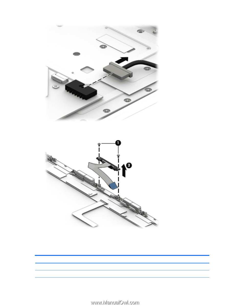
2.
Remove the two screws
(1)
that secures the POGO (10-pin) docking connector board to the display panel
assembly, and then remove the POGO (10-pin) docking connector board
(2)
.
Reverse this procedure to install the POGO (10-pin) docking connector board.
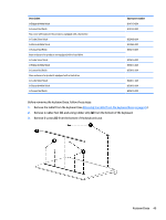
Keyboard base
Description
Spare part number
Top cover with keyboard for products not equipped with a hard drive
In Turbo Silver finish
814718-001
44
Chapter 5
Removal and replacement procedures for Authorized Service Provider parts