HP Pavilion 15-aw000 Maintenance and Service Guide - Page 55
I/O board, Remove the I/O board
 |
View all HP Pavilion 15-aw000 manuals
Add to My Manuals
Save this manual to your list of manuals |
Page 55 highlights
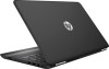
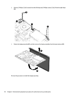
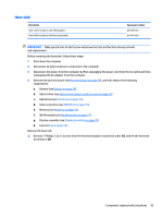
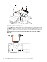
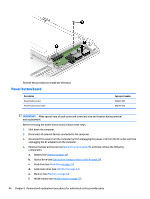
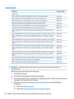
I/O board Description I/O board I/O board cable Spare part number 856370-001 856349-001 IMPORTANT: Make special note of each screw and screw lock size and location during removal and replacement Before removing the I/O board, follow these steps: 1. Shut down the computer. 2. Disconnect all external devices connected to the computer. 3. Disconnect the power from the computer by first unplugging the power cord from the AC outlet and then unplugging the AC adapter from the computer. 4. Remove the base enclosure (see Base enclosure on page 28), and then remove the following components: a. Battery (see Battery on page 30). b. Optical drive (see Optical drive (select products only) on page 26). c. Hard drive (see Hard drive on page 31). d. Solid-state drive (see SSD (M.2) on page 33). e. Memory (see Memory on page 34). f. WLAN module (see WLAN module on page 37). g. Display assembly (see Display assembly on page 39). h. Fan (see Fan on page 41). i. Heat sink (see Heat sink on page 43). Remove the I/O board: ▲ Disconnect the I/O board cable (1), remove 1 Phillips 2.0x2.5 screw (2), and then lift the I/O board to remove it (3). Component replacement procedures 45
-
 1
1 -
2
-
3
-
4
-
5
-
6
-
7
-
8
-
9
-
10
-
11
-
12
-
13
-
14
-
15
-
16
-
17
-
18
-
19
-
20
-
21
-
22
-
23
-
24
-
25
-
26
-
27
-
28
-
29
-
30
-
31
-
32
-
33
-
34
-
35
-
36
-
37
-
38
-
39
-
40
-
41
-
42
-
43
-
44
-
45
-
46
-
47
-
48
-
49
-
 50
50 -
 51
51 -
 52
52 -
 53
53 -
 54
54 -
 55
55 -
 56
56 -
 57
57 -
 58
58 -
 59
59 -
 60
60 -
61
-
62
-
63
-
64
-
65
-
66
-
67
-
68
-
69
-
70
-
71
-
72
-
73
-
74
-
75
-
76
-
77
-
78
-
79
-
80
-
81
-
82
-
83
-
84
-
85
-
86
-
87
-
88
-
89
-
90
-
91
-
92
-
93
-
94
 |
 |