HP Pavilion 15-b100 HP Pavilion Sleekbook 15 and HP Pavilion Ultrabook 15 Main - Page 81
Display Assembly, Description, Spare part number, Antenna Kit, Display Panel Cable Kit
 |
View all HP Pavilion 15-b100 manuals
Add to My Manuals
Save this manual to your list of manuals |
Page 81 highlights
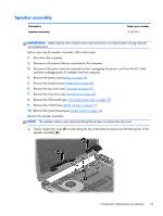
Display Assembly Description Antenna Kit (includes left and right wireless antenna cables and transceivers) Display Panel Cable Kit (includes display panel cable and webcam/microphone module cable) Display enclosure: ● Ruby red ● Sparkling black Display Hinge Kit (includes left and right display hinges and brackets) Webcam/microphone module Antenna Spare part number 701676-001 701681-001 701677-001 701678-001 701683-001 707767-001 701676-001 IMPORTANT: Make special note of each screw and screw lock size and location during removal and replacement. Before removing the display assembly, follow these steps: 1. Shut down the computer. 2. Disconnect all external devices connected to the computer. 3. Disconnect the power from the computer by first unplugging the power cord from the AC outlet and then unplugging the AC adapter from the computer. 4. Remove the battery (see Battery on page 34). 5. Remove the display panel (see Display panel on page 36). 6. Remove the keyboard (see Keyboard on page 39). 7. Remove the top cover (see Top cover on page 43). 8. Remove the hard drive (see Hard drive on page 47). 9. Remove the USB board (see USB board/Audio jack on page 50). 10. Remove the WLAN (see WLAN module on page 51). 11. Remove the system board (see System board on page 54). Remove the display assembly: Component replacement procedures 73
-
 1
1 -
2
-
3
-
4
-
5
-
6
-
7
-
8
-
9
-
10
-
11
-
12
-
13
-
14
-
15
-
16
-
17
-
18
-
19
-
20
-
21
-
22
-
23
-
24
-
25
-
26
-
27
-
28
-
29
-
30
-
31
-
32
-
33
-
34
-
35
-
36
-
37
-
38
-
39
-
40
-
41
-
42
-
43
-
44
-
45
-
46
-
47
-
48
-
49
-
50
-
51
-
52
-
53
-
54
-
55
-
56
-
57
-
58
-
59
-
60
-
61
-
62
-
63
-
64
-
65
-
66
-
67
-
68
-
69
-
70
-
71
-
72
-
73
-
74
-
75
-
 76
76 -
 77
77 -
 78
78 -
 79
79 -
 80
80 -
 81
81 -
 82
82 -
 83
83 -
 84
84 -
 85
85 -
 86
86 -
87
-
88
-
89
-
90
-
91
-
92
-
93
-
94
-
95
-
96
-
97
-
98
-
99
-
100
-
101
-
102
-
103
-
104
-
105
-
106
-
107
-
108
-
109
-
110
-
111
-
112
-
113
 |
 |
