HP Pavilion 15-b100 HP Pavilion Sleekbook 15 and HP Pavilion Ultrabook 15 Main - Page 83
built into the display enclosure., Release the wireless antenna cables from the clips
 |
View all HP Pavilion 15-b100 manuals
Add to My Manuals
Save this manual to your list of manuals |
Page 83 highlights
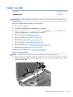
3. Remove the two top screws (1) and two bottom screws (2) from the display bracket and lift the display brackets (3) to remove them. 4. If it is necessary to replace the display panel cable: a. Gently remove the cable from the routing clips (1). b. Detach and release the WLAN module (the WLAN module is attached to the display enclosure with double-sided tape), and remove the cables (2). 5. If it is necessary to replace the wireless antenna cables and transceivers: a. Release the wireless antenna cables from the clips (1) built into the display enclosure. b. Release the wireless antenna transceivers (2) from the display enclosure. (The wireless antenna transceivers are attached to the display enclosure with double-sided tape.) Component replacement procedures 75
-
 1
1 -
2
-
3
-
4
-
5
-
6
-
7
-
8
-
9
-
10
-
11
-
12
-
13
-
14
-
15
-
16
-
17
-
18
-
19
-
20
-
21
-
22
-
23
-
24
-
25
-
26
-
27
-
28
-
29
-
30
-
31
-
32
-
33
-
34
-
35
-
36
-
37
-
38
-
39
-
40
-
41
-
42
-
43
-
44
-
45
-
46
-
47
-
48
-
49
-
50
-
51
-
52
-
53
-
54
-
55
-
56
-
57
-
58
-
59
-
60
-
61
-
62
-
63
-
64
-
65
-
66
-
67
-
68
-
69
-
70
-
71
-
72
-
73
-
74
-
75
-
76
-
77
-
 78
78 -
 79
79 -
 80
80 -
 81
81 -
 82
82 -
 83
83 -
 84
84 -
 85
85 -
 86
86 -
 87
87 -
 88
88 -
89
-
90
-
91
-
92
-
93
-
94
-
95
-
96
-
97
-
98
-
99
-
100
-
101
-
102
-
103
-
104
-
105
-
106
-
107
-
108
-
109
-
110
-
111
-
112
-
113
 |
 |
