HP Pavilion Notebook - 14-v134ca HP Pavilion 14 Notebook PC HP Pavilion 14 Tou - Page 70
USB/audio board cable, When replacing the system board
 |
View all HP Pavilion Notebook - 14-v134ca manuals
Add to My Manuals
Save this manual to your list of manuals |
Page 70 highlights
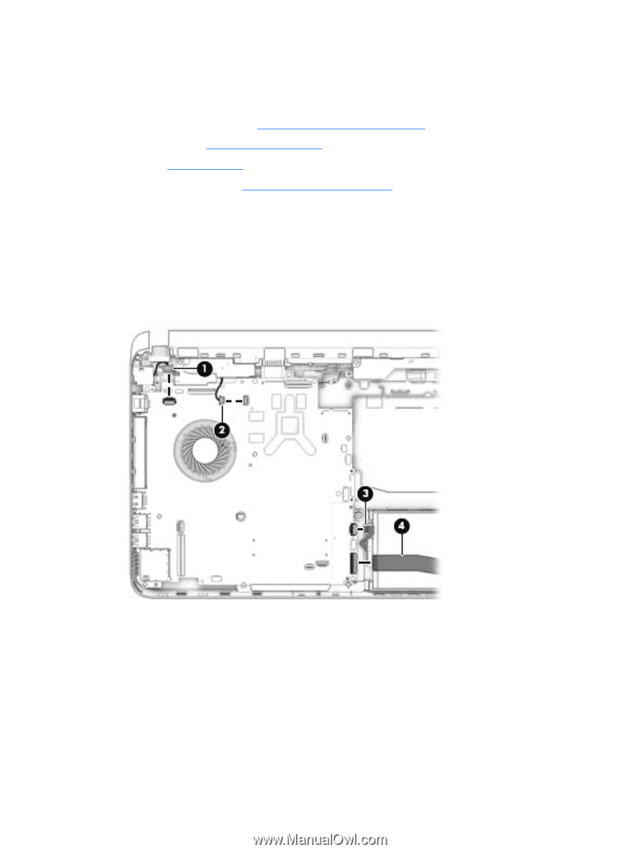
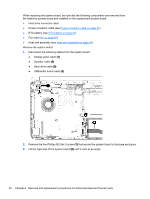
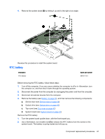
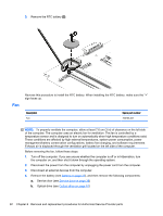
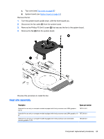
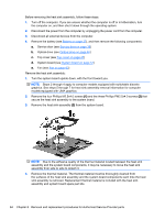
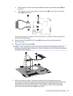
When replacing the system board, be sure that the following components are removed from the defective system board and installed on the replacement system board: ● Hard drive connector cable ● Power connector cable (see Power connector cable on page 67) ● RTC battery (see RTC battery on page 61) ● Fan (see Fan on page 62) ● Heat sink assembly (see Heat sink assembly on page 63) Remove the system board: 1. Disconnect the following cables from the system board: ● Display panel cable (1) ● Speaker cable (2) ● Hard drive cable (3) ● USB/audio board cable (4) 2. Remove the five Phillips M2.5x4.0 screw (1) that secure the system board to the base enclosure. 3. Lift the right side of the system board (2) until it rests at an angle. 60 Chapter 6 Removal and replacement procedures for Authorized Service Provider parts
-
 1
1 -
2
-
3
-
4
-
5
-
6
-
7
-
8
-
9
-
10
-
11
-
12
-
13
-
14
-
15
-
16
-
17
-
18
-
19
-
20
-
21
-
22
-
23
-
24
-
25
-
26
-
27
-
28
-
29
-
30
-
31
-
32
-
33
-
34
-
35
-
36
-
37
-
38
-
39
-
40
-
41
-
42
-
43
-
44
-
45
-
46
-
47
-
48
-
49
-
50
-
51
-
52
-
53
-
54
-
55
-
56
-
57
-
58
-
59
-
60
-
61
-
62
-
63
-
64
-
 65
65 -
 66
66 -
 67
67 -
 68
68 -
 69
69 -
 70
70 -
 71
71 -
 72
72 -
 73
73 -
 74
74 -
 75
75 -
76
-
77
-
78
-
79
-
80
-
81
-
82
-
83
-
84
-
85
-
86
-
87
-
88
-
89
-
90
-
91
-
92
-
93
-
94
-
95
-
96
-
97
-
98
-
99
-
100
-
101
-
102
-
103
-
104
-
105
 |
 |