HP Pavilion Notebook - 14-v134ca HP Pavilion 14 Notebook PC HP Pavilion 14 Tou - Page 80
that secure the display assembly to, the base enclosure.
 |
View all HP Pavilion Notebook - 14-v134ca manuals
Add to My Manuals
Save this manual to your list of manuals |
Page 80 highlights
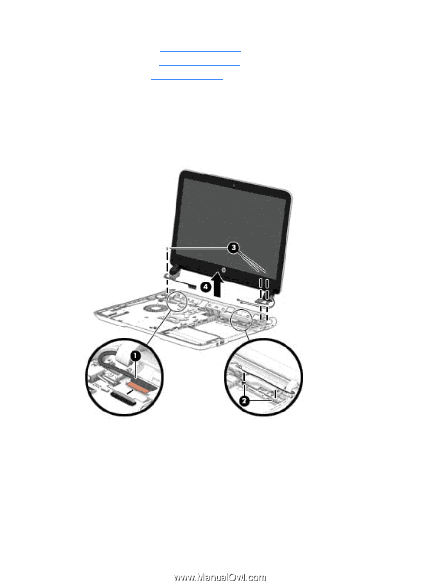
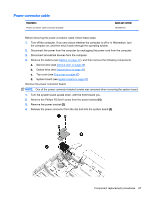
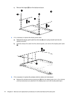
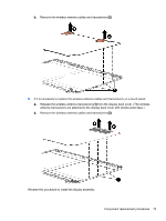
a. Service door (see Service door on page 38) b. Optical drive (see Optical drive on page 40) c. Top cover (see Top cover on page 47) Remove the display assembly: 1. Disconnect the display cable (1) by flipping open the connector and lifting the cable. 2. Release the wireless antenna cables from the clips (2) built into the base enclosure. 3. Remove the three Phillips PM2.5×4.0 screws (3) that secure the display assembly to the base enclosure. 4. Remove the display assembly (4). If it is necessary to replace any of the display assembly subcomponents: 1. If it is necessary to replace the webcamera/microphone module: a. Disconnect the webcamera/microphone module cable (1) from the webcamera/microphone module. (The webcamera/microphone module cable is part of the display panel cable.) 70 Chapter 6 Removal and replacement procedures for Authorized Service Provider parts
-
 1
1 -
2
-
3
-
4
-
5
-
6
-
7
-
8
-
9
-
10
-
11
-
12
-
13
-
14
-
15
-
16
-
17
-
18
-
19
-
20
-
21
-
22
-
23
-
24
-
25
-
26
-
27
-
28
-
29
-
30
-
31
-
32
-
33
-
34
-
35
-
36
-
37
-
38
-
39
-
40
-
41
-
42
-
43
-
44
-
45
-
46
-
47
-
48
-
49
-
50
-
51
-
52
-
53
-
54
-
55
-
56
-
57
-
58
-
59
-
60
-
61
-
62
-
63
-
64
-
65
-
66
-
67
-
68
-
69
-
70
-
71
-
72
-
73
-
74
-
 75
75 -
 76
76 -
 77
77 -
 78
78 -
 79
79 -
 80
80 -
 81
81 -
 82
82 -
 83
83 -
 84
84 -
 85
85 -
86
-
87
-
88
-
89
-
90
-
91
-
92
-
93
-
94
-
95
-
96
-
97
-
98
-
99
-
100
-
101
-
102
-
103
-
104
-
105
 |
 |