HP Pavilion TouchSmart 11-e040ca HP Pavilion TouchSmart 11 Notebook PC - Maint - Page 43
Removal and replacement procedures for Authorized Service Provider parts
 |
View all HP Pavilion TouchSmart 11-e040ca manuals
Add to My Manuals
Save this manual to your list of manuals |
Page 43 highlights
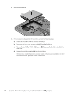
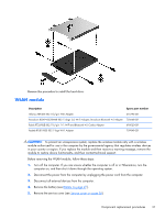
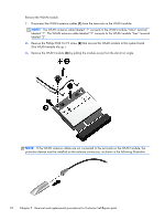
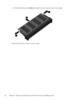
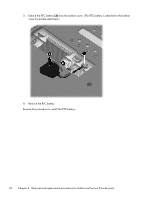
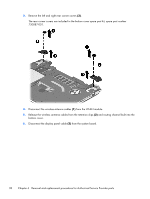
6 Removal and replacement procedures for Authorized Service Provider parts CAUTION: Components described in this chapter should only be accessed by an authorized service provider. Accessing these parts can damage the computer or void the warranty. Component replacement procedures This chapter provides removal and replacement procedures for Authorized Service Provider only parts. There are as many as 44 screws that must be removed, replaced, and/or loosened when servicing the computer. Make special note of each screw size and location during removal and replacement. RTC battery Description RTC battery (includes double-sided tape) Spare part number 738824-001 Before removing the RTC battery, follow these steps: 1. Turn off the computer. If you are unsure whether the computer is off or in Hibernation, turn the computer on, and then shut it down through the operating system. 2. Disconnect the power from the computer by unplugging the power cord from the computer. 3. Disconnect all external devices from the computer. 4. Remove the battery (see Battery on page 27). 5. Remove the service cover (see Service cover on page 28). Remove the RTC battery: 1. Disconnect the RTC battery cable (1) from the system board. 2. Release the RTC battery cable (2) from the routing channel built into the bottom cover. Component replacement procedures 35
-
 1
1 -
2
-
3
-
4
-
5
-
6
-
7
-
8
-
9
-
10
-
11
-
12
-
13
-
14
-
15
-
16
-
17
-
18
-
19
-
20
-
21
-
22
-
23
-
24
-
25
-
26
-
27
-
28
-
29
-
30
-
31
-
32
-
33
-
34
-
35
-
36
-
37
-
 38
38 -
 39
39 -
 40
40 -
 41
41 -
 42
42 -
 43
43 -
 44
44 -
 45
45 -
 46
46 -
 47
47 -
 48
48 -
49
-
50
-
51
-
52
-
53
-
54
-
55
-
56
-
57
-
58
-
59
-
60
-
61
-
62
-
63
-
64
-
65
-
66
-
67
-
68
-
69
-
70
-
71
-
72
-
73
-
74
-
75
-
76
-
77
-
78
-
79
-
80
-
81
-
82
-
83
-
84
-
85
 |
 |
