HP Pavilion TouchSmart 11-e040ca HP Pavilion TouchSmart 11 Notebook PC - Maint - Page 61
System board, WLAN module see
 |
View all HP Pavilion TouchSmart 11-e040ca manuals
Add to My Manuals
Save this manual to your list of manuals |
Page 61 highlights
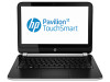
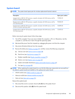
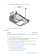
System board NOTE: The system board spare part kit includes replacement thermal material. Description Equipped with an AMD A6-1450 processor, a graphics subsystem with UMA memory, and the Windows 8 Standard operating system Equipped with an AMD A6-1450 processor, a graphics subsystem with UMA memory, and the Linux operating system Equipped with an AMD A4-1250 processor, a graphics subsystem with UMA memory, and the Windows 8 Standard operating system Equipped with an AMD A4-1250 processor, a graphics subsystem with UMA memory, and the Linux operating system Spare part number 730894-501 730894-001 730893-501 730893-001 Before removing the system board, follow these steps: 1. Turn off the computer. If you are unsure whether the computer is off or in Hibernation, turn the computer on, and then shut it down through the operating system. 2. Disconnect the power from the computer by unplugging the power cord from the computer. 3. Disconnect all external devices from the computer. 4. Remove the battery (see Battery on page 27), and then remove the following components: a. Service cover (see Service cover on page 28) b. Hard drive (see Hard drive on page 29) c. Display assembly (see Display assembly on page 37) d. Bottom cover (see Bottom cover on page 42) e. Media card reader board (see Media card reader board on page 48) f. Fan (see Fan on page 49) NOTE: When replacing the system board, be sure that the following components are removed from the defective system board and installed on the replacement system board: ● WLAN module (see WLAN module on page 31) ● Memory module (see Memory module on page 33) ● Heat sink (see Heat sink on page 55) Remove the system board: 1. Disconnect the monitor connector board cable (1) from the system board. 2. Disconnect the speaker cable (2) from the system board. Component replacement procedures 53
-
 1
1 -
2
-
3
-
4
-
5
-
6
-
7
-
8
-
9
-
10
-
11
-
12
-
13
-
14
-
15
-
16
-
17
-
18
-
19
-
20
-
21
-
22
-
23
-
24
-
25
-
26
-
27
-
28
-
29
-
30
-
31
-
32
-
33
-
34
-
35
-
36
-
37
-
38
-
39
-
40
-
41
-
42
-
43
-
44
-
45
-
46
-
47
-
48
-
49
-
50
-
51
-
52
-
53
-
54
-
55
-
 56
56 -
 57
57 -
 58
58 -
 59
59 -
 60
60 -
 61
61 -
 62
62 -
 63
63 -
 64
64 -
 65
65 -
 66
66 -
67
-
68
-
69
-
70
-
71
-
72
-
73
-
74
-
75
-
76
-
77
-
78
-
79
-
80
-
81
-
82
-
83
-
84
-
85
 |
 |