HP Pavilion TouchSmart 15-n300 Maintenance and Service Guide - Page 65
Top cover, Remove
 |
View all HP Pavilion TouchSmart 15-n300 manuals
Add to My Manuals
Save this manual to your list of manuals |
Page 65 highlights
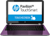
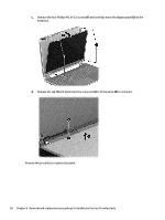
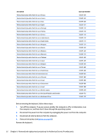
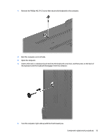
Top cover NOTE: The top cover spare part kit includes the TouchPad buttons, TouchPad board and TouchPad cable. Description In pearl white finish In flyer red finish In revolutionary blue finish In regal purple finish In sparkling black finish In aluminum metal finish In mineral black finish In Goji berry finish In hazel berry finish In raspberry finish Spare part number 732091-001 732092-001 732093-001 732094-001 732095-001 732096-001 737178-001 737179-001 737180-001 737181-001 IMPORTANT: Make special note of each screw and screw lock size and location during removal and replacement Before removing the top cover, follow these steps: 1. Shut down the computer. 2. Disconnect all external devices connected to the computer. 3. Disconnect the power from the computer by first unplugging the power cord from the AC outlet and then unplugging the AC adapter from the computer. 4. Remove the battery (see Battery on page 40), and then remove the following components: a. Optical drive (see Optical drive on page 45). b. Remove the service door (see Service door on page 42). c. Remove the WLAN module (see WLAN module on page 44). d. Remove the memory module (see Memory module on page 42). e. Keyboard (see Keyboard on page 51). Remove the top cover: 1. Remove the seven Phillips M2.5×3.0 screws that secure the top cover to the base enclosure. Component replacement procedures 55
-
 1
1 -
2
-
3
-
4
-
5
-
6
-
7
-
8
-
9
-
10
-
11
-
12
-
13
-
14
-
15
-
16
-
17
-
18
-
19
-
20
-
21
-
22
-
23
-
24
-
25
-
26
-
27
-
28
-
29
-
30
-
31
-
32
-
33
-
34
-
35
-
36
-
37
-
38
-
39
-
40
-
41
-
42
-
43
-
44
-
45
-
46
-
47
-
48
-
49
-
50
-
51
-
52
-
53
-
54
-
55
-
56
-
57
-
58
-
59
-
 60
60 -
 61
61 -
 62
62 -
 63
63 -
 64
64 -
 65
65 -
 66
66 -
 67
67 -
 68
68 -
 69
69 -
 70
70 -
71
-
72
-
73
-
74
-
75
-
76
-
77
-
78
-
79
-
80
-
81
-
82
-
83
-
84
-
85
-
86
-
87
-
88
-
89
-
90
-
91
-
92
-
93
-
94
-
95
-
96
-
97
-
98
-
99
-
100
-
101
-
102
-
103
-
104
-
105
-
106
-
107
-
108
-
109
-
110
-
111
-
112
-
113
-
114
-
115
-
116
-
117
-
118
-
119
-
120
-
121
-
122
-
123
-
124
 |
 |
