HP Pavilion TouchSmart 15-n300 Maintenance and Service Guide - Page 96
Flex the inside edges of the bottom edge, subcomponent spare part kits.
 |
View all HP Pavilion TouchSmart 15-n300 manuals
Add to My Manuals
Save this manual to your list of manuals |
Page 96 highlights
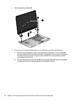
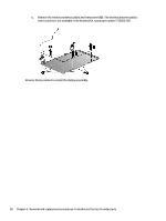
2. Remove the display assembly (3). 3. If it is necessary to replace the display bezel or any of the display assembly subcomponents: a. Remove the two display bezel screw covers (1) and the two Phillips M2.5×5.0 screws (2) that secure the display bezel to the display assembly. The display bezel screw covers are included in the display bezel spare part kit, spare part number 676644-001, and in all display assembly subcomponent spare part kits. b. Flex the inside edges of the bottom edge (3), the left and right sides (4), and the top edge (5) of the display bezel until the bezel disengages from the display enclosure. 86 Chapter 6 Removal and replacement procedures for Authorized Service Provider parts
-
 1
1 -
2
-
3
-
4
-
5
-
6
-
7
-
8
-
9
-
10
-
11
-
12
-
13
-
14
-
15
-
16
-
17
-
18
-
19
-
20
-
21
-
22
-
23
-
24
-
25
-
26
-
27
-
28
-
29
-
30
-
31
-
32
-
33
-
34
-
35
-
36
-
37
-
38
-
39
-
40
-
41
-
42
-
43
-
44
-
45
-
46
-
47
-
48
-
49
-
50
-
51
-
52
-
53
-
54
-
55
-
56
-
57
-
58
-
59
-
60
-
61
-
62
-
63
-
64
-
65
-
66
-
67
-
68
-
69
-
70
-
71
-
72
-
73
-
74
-
75
-
76
-
77
-
78
-
79
-
80
-
81
-
82
-
83
-
84
-
85
-
86
-
87
-
88
-
89
-
90
-
 91
91 -
 92
92 -
 93
93 -
 94
94 -
 95
95 -
 96
96 -
 97
97 -
 98
98 -
 99
99 -
 100
100 -
 101
101 -
102
-
103
-
104
-
105
-
106
-
107
-
108
-
109
-
110
-
111
-
112
-
113
-
114
-
115
-
116
-
117
-
118
-
119
-
120
-
121
-
122
-
123
-
124
 |
 |

2.
Remove the display assembly
(3)
.
3.
If it is necessary to replace the display bezel or any of the display assembly subcomponents:
a.
Remove the two display bezel screw covers
(1)
and the two Phillips M2.5×5.0 screws
(2)
that
secure the display bezel to the display assembly. The display bezel screw covers are included in
the display bezel spare part kit, spare part number 676644-001, and in all display assembly
subcomponent spare part kits.
b.
Flex the inside edges of the bottom edge
(3)
, the left and right sides
(4)
, and the top edge
(5)
of
the display bezel until the bezel disengages from the display enclosure.
86
Chapter 6
Removal and replacement procedures for Authorized Service Provider parts