HP Pavilion TouchSmart 15-n300 Maintenance and Service Guide - Page 97
the display enclosure., that secure the display panel
 |
View all HP Pavilion TouchSmart 15-n300 manuals
Add to My Manuals
Save this manual to your list of manuals |
Page 97 highlights
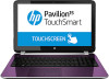
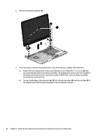
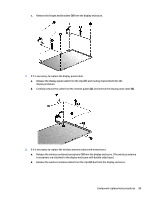
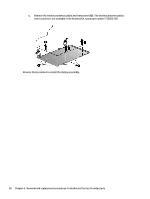
c. Remove the display bezel (6). The display bezel is available using spare part number 725617-001. CAUTION: Be sure the work surface is clear of all tools, screws, and computer components before turning the display panel upside down on the work surface. 4. If it is necessary to replace the display panel: a. Remove the four Phillips M2.0×3.5 screws (1) that secure the display panel to the display enclosure. b. Lift the top edge of the display panel (2) and turn the display panel upside down. c. Release the connector (1) that secures the display panel cable connector to the display panel. Component replacement procedures 87
-
 1
1 -
2
-
3
-
4
-
5
-
6
-
7
-
8
-
9
-
10
-
11
-
12
-
13
-
14
-
15
-
16
-
17
-
18
-
19
-
20
-
21
-
22
-
23
-
24
-
25
-
26
-
27
-
28
-
29
-
30
-
31
-
32
-
33
-
34
-
35
-
36
-
37
-
38
-
39
-
40
-
41
-
42
-
43
-
44
-
45
-
46
-
47
-
48
-
49
-
50
-
51
-
52
-
53
-
54
-
55
-
56
-
57
-
58
-
59
-
60
-
61
-
62
-
63
-
64
-
65
-
66
-
67
-
68
-
69
-
70
-
71
-
72
-
73
-
74
-
75
-
76
-
77
-
78
-
79
-
80
-
81
-
82
-
83
-
84
-
85
-
86
-
87
-
88
-
89
-
90
-
91
-
 92
92 -
 93
93 -
 94
94 -
 95
95 -
 96
96 -
 97
97 -
 98
98 -
 99
99 -
 100
100 -
 101
101 -
 102
102 -
103
-
104
-
105
-
106
-
107
-
108
-
109
-
110
-
111
-
112
-
113
-
114
-
115
-
116
-
117
-
118
-
119
-
120
-
121
-
122
-
123
-
124
 |
 |

c.
Remove the display bezel
(6)
. The display bezel is available using spare part number 725617-001.
CAUTION:
Be sure the work surface is clear of all tools, screws, and computer components before
turning the display panel upside down on the work surface.
4.
If it is necessary to replace the display panel:
a.
Remove the four Phillips M2.0×3.5 screws
(1)
that secure the display panel to
the display enclosure.
b.
Lift the top edge of the display panel
(2)
and turn the display panel upside down.
c.
Release the connector
(1)
that secures the display panel cable connector to the display panel.
Component replacement procedures
87