HP Pavilion dv4-3000 HP Pavilion dv4 Entertainment PC - Maintenance and Servic - Page 76
System board, Display assembly see
 |
View all HP Pavilion dv4-3000 manuals
Add to My Manuals
Save this manual to your list of manuals |
Page 76 highlights
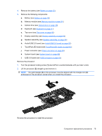
System board NOTE: The system board kit includes replacement thermal material. Description System board Spare part number 641760-001 When replacing the system board, be sure that the following components are removed from the defective system board and installed on the replacement system board: ● RTC battery (see RTC battery on page 45) ● Memory module (see Memory module on page 34) ● WLAN module (see WLAN module on page 43) ● Fan/heat sink assembly (see Fan/heat sink assembly on page 70) ● Processor (see Processor on page 72) Before removing the system board, follow these steps: 1. Shut down the computer. If you are unsure whether the computer is off or in Hibernation, turn the computer on, and then shut it down through the operating system. 2. Disconnect all external devices connected to the computer. 3. Disconnect the power from the computer by first unplugging the power cord from the AC outlet and then unplugging the AC adapter from the computer. 4. Remove the following components: a. Battery (see Battery on page 33) b. Memory module (see Memory module on page 34 ) c. Optical drive (see Optical drive on page 39) d. Keyboard (see Keyboard on page 41) e. Top cover (see Top cover on page 46) f. Display assembly (see Display assembly on page 52) g. Speaker assembly (see Speaker assembly on page 59) h. Audio/USB 2.0 board (see Audio/USB 2.0 board on page 60) i. Power connector (see Power connector on page 66) 1. Position the computer right-side up, with the front toward you. 2. Disconnect the optical drive cable (1) from the system board. 3. Disconnect the hard drive cable (2) from the system board . 68 Chapter 4 Removal and replacement procedures
-
 1
1 -
2
-
3
-
4
-
5
-
6
-
7
-
8
-
9
-
10
-
11
-
12
-
13
-
14
-
15
-
16
-
17
-
18
-
19
-
20
-
21
-
22
-
23
-
24
-
25
-
26
-
27
-
28
-
29
-
30
-
31
-
32
-
33
-
34
-
35
-
36
-
37
-
38
-
39
-
40
-
41
-
42
-
43
-
44
-
45
-
46
-
47
-
48
-
49
-
50
-
51
-
52
-
53
-
54
-
55
-
56
-
57
-
58
-
59
-
60
-
61
-
62
-
63
-
64
-
65
-
66
-
67
-
68
-
69
-
70
-
 71
71 -
 72
72 -
 73
73 -
 74
74 -
 75
75 -
 76
76 -
 77
77 -
 78
78 -
 79
79 -
 80
80 -
 81
81 -
82
-
83
-
84
-
85
-
86
-
87
-
88
-
89
-
90
-
91
-
92
-
93
-
94
-
95
-
96
-
97
-
98
-
99
-
100
-
101
-
102
-
103
-
104
-
105
-
106
-
107
-
108
-
109
-
110
-
111
-
112
-
113
 |
 |
