HP Presario CQ40-200 Compaq Presario CQ40 Notebook PC - Maintenance and Servic - Page 61
Memory modules are designed with a notch, by pulling it away from the slot at an angle.
 |
View all HP Presario CQ40-200 manuals
Add to My Manuals
Save this manual to your list of manuals |
Page 61 highlights
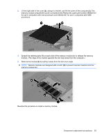
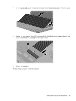
3. Lift the right side of the cover (2), swing it to the left, and lift the cover off the computer (3). The memory module compartment cover is included in the Plastics Kit, spare part number 486862-001 for use in computers with Intel processors and 498322-001 for use in computers with AMD processors. 4. Spread the retaining tabs (1) on each side of the memory module slot to release the memory module. (The edge of the module opposite the slot rises away from the computer.) 5. Remove the module (2) by pulling it away from the slot at an angle. NOTE: Memory modules are designed with a notch (3) to prevent incorrect insertion into the memory module slot. Reverse this procedure to install a memory module. Component replacement procedures 53
-
 1
1 -
2
-
3
-
4
-
5
-
6
-
7
-
8
-
9
-
10
-
11
-
12
-
13
-
14
-
15
-
16
-
17
-
18
-
19
-
20
-
21
-
22
-
23
-
24
-
25
-
26
-
27
-
28
-
29
-
30
-
31
-
32
-
33
-
34
-
35
-
36
-
37
-
38
-
39
-
40
-
41
-
42
-
43
-
44
-
45
-
46
-
47
-
48
-
49
-
50
-
51
-
52
-
53
-
54
-
55
-
 56
56 -
 57
57 -
 58
58 -
 59
59 -
 60
60 -
 61
61 -
 62
62 -
 63
63 -
 64
64 -
 65
65 -
 66
66 -
67
-
68
-
69
-
70
-
71
-
72
-
73
-
74
-
75
-
76
-
77
-
78
-
79
-
80
-
81
-
82
-
83
-
84
-
85
-
86
-
87
-
88
-
89
-
90
-
91
-
92
-
93
-
94
-
95
-
96
-
97
-
98
-
99
-
100
-
101
-
102
-
103
-
104
-
105
-
106
-
107
-
108
-
109
-
110
-
111
-
112
-
113
-
114
-
115
-
116
-
117
-
118
-
119
-
120
-
121
-
122
-
123
-
124
-
125
-
126
-
127
-
128
-
129
-
130
-
131
-
132
-
133
-
134
-
135
-
136
-
137
-
138
-
139
-
140
-
141
-
142
-
143
-
144
-
145
-
146
-
147
-
148
-
149
-
150
-
151
-
152
-
153
-
154
-
155
 |
 |
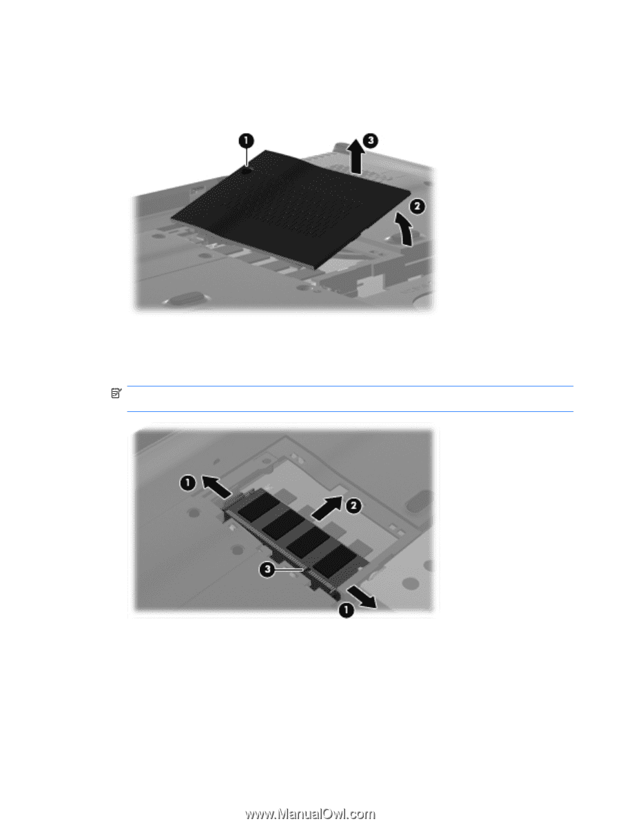
3.
Lift the right side of the cover
(2)
, swing it to the left, and lift the cover off the computer
(3)
. The
memory module compartment cover is included in the Plastics Kit, spare part number 486862-001
for use in computers with Intel processors and 498322-001 for use in computers with AMD
processors.
4.
Spread the retaining tabs
(1)
on each side of the memory module slot to release the memory
module. (The edge of the module opposite the slot rises away from the computer.)
5.
Remove the module
(2)
by pulling it away from the slot at an angle.
NOTE:
Memory modules are designed with a notch
(3)
to prevent incorrect insertion into the
memory module slot.
Reverse this procedure to install a memory module.
Component replacement procedures
53