HP Presario CQ40-200 Compaq Presario CQ40 Notebook PC - Maintenance and Servic - Page 68
Display assembly, Remove the following components
 |
View all HP Presario CQ40-200 manuals
Add to My Manuals
Save this manual to your list of manuals |
Page 68 highlights
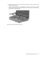
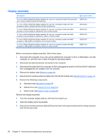
Display assembly Description Spare part number 14.1-inch, WXGA, BrightView display assembly for use only in computer models Intel processors 487281-001 with a camera module (includes microphones) 14.1-inch, WXGA, BrightView display assembly for use only in computer models with Intel processors without a camera module (includes microphones) 487280-001 14.1-inch, WXGA, BrightView display assembly for use only in computer models with AMD processors, discrete graphics subsystems, and a camera module 487353-001 14.1-inch, WXGA, BrightView display assembly for use only in computer models with AMD processors, discrete graphics subsystems, without a camera module 487352-001 14.1-inch, WXGA, BrightView display assembly for use only in computer models with AMD processors, UMA graphics subsystems, and a camera module 502978-001 14.1-inch, WXGA, BrightView display assembly for use only in computer models with AMD processors, UMA graphics subsystems, without a camera module 502977-001 Before removing the display assembly, follow these steps: 1. Shut down the computer. If you are unsure whether the computer is off or in Hibernation, turn the computer on, and then shut it down through the operating system. 2. Disconnect all external devices connected to the computer. 3. Disconnect the power from the computer by first unplugging the power cord from the AC outlet and then unplugging the AC adapter from the computer. 4. Remove the battery (see Battery on page 41). 5. Disconnect the wireless antenna cables from the WLAN module (see WLAN module on page 47). 6. Remove the following components: a. Keyboard (see Keyboard on page 54) b. Optical drive (see Optical drive on page 42) c. Switch cover (see Switch cover on page 56) Remove the display assembly: 1. Turn the computer display-side up, with the front toward you. 2. Open the display as far as possible. 3. Remove the wireless antenna cables (1) from the hole in the system board and the routing channels built into the top cover. 60 Chapter 4 Removal and replacement procedures
-
 1
1 -
2
-
3
-
4
-
5
-
6
-
7
-
8
-
9
-
10
-
11
-
12
-
13
-
14
-
15
-
16
-
17
-
18
-
19
-
20
-
21
-
22
-
23
-
24
-
25
-
26
-
27
-
28
-
29
-
30
-
31
-
32
-
33
-
34
-
35
-
36
-
37
-
38
-
39
-
40
-
41
-
42
-
43
-
44
-
45
-
46
-
47
-
48
-
49
-
50
-
51
-
52
-
53
-
54
-
55
-
56
-
57
-
58
-
59
-
60
-
61
-
62
-
 63
63 -
 64
64 -
 65
65 -
 66
66 -
 67
67 -
 68
68 -
 69
69 -
 70
70 -
 71
71 -
 72
72 -
 73
73 -
74
-
75
-
76
-
77
-
78
-
79
-
80
-
81
-
82
-
83
-
84
-
85
-
86
-
87
-
88
-
89
-
90
-
91
-
92
-
93
-
94
-
95
-
96
-
97
-
98
-
99
-
100
-
101
-
102
-
103
-
104
-
105
-
106
-
107
-
108
-
109
-
110
-
111
-
112
-
113
-
114
-
115
-
116
-
117
-
118
-
119
-
120
-
121
-
122
-
123
-
124
-
125
-
126
-
127
-
128
-
129
-
130
-
131
-
132
-
133
-
134
-
135
-
136
-
137
-
138
-
139
-
140
-
141
-
142
-
143
-
144
-
145
-
146
-
147
-
148
-
149
-
150
-
151
-
152
-
153
-
154
-
155
 |
 |