HP Presario CQ40-200 Compaq Presario CQ40 Notebook PC - Maintenance and Servic - Page 75
Top cover, Two Phillips PM2.0×3.0 screws
 |
View all HP Presario CQ40-200 manuals
Add to My Manuals
Save this manual to your list of manuals |
Page 75 highlights
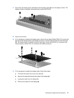
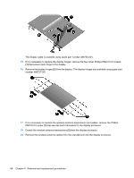
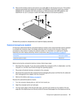
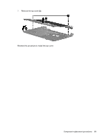
Top cover Description Top cover (includes TouchPad and cable) Spare part number 487300-001 Before removing the top cover, follow these steps: 1. Shut down the computer. If you are unsure whether the computer is off or in Hibernation, turn the computer on, and then shut it down through the operating system. 2. Disconnect all external devices connected to the computer. 3. Disconnect the power from the computer by first unplugging the power cord from the AC outlet and then unplugging the AC adapter from the computer. 4. Remove the battery (see Battery on page 41). 5. Remove the following components: a. Hard drive (see Hard drive on page 44) b. Optical drive (see Optical drive on page 42) c. Keyboard (see Keyboard on page 54) d. Switch cover (see Switch cover on page 56) e. Speaker assembly (see Speaker assembly on page 58) f. Display assembly (see Display assembly on page 60) Remove the top cover: 1. Turn the computer upside down, with the front toward you. 2. Remove the seven screws that secure the top cover to the computer. ● (1) Three Phillips PM2.5×10.0 screws ● (2) Two Phillips PM2.5×5.0 screws ● (3) Two Phillips PM2.0×3.0 screws Component replacement procedures 67
-
 1
1 -
2
-
3
-
4
-
5
-
6
-
7
-
8
-
9
-
10
-
11
-
12
-
13
-
14
-
15
-
16
-
17
-
18
-
19
-
20
-
21
-
22
-
23
-
24
-
25
-
26
-
27
-
28
-
29
-
30
-
31
-
32
-
33
-
34
-
35
-
36
-
37
-
38
-
39
-
40
-
41
-
42
-
43
-
44
-
45
-
46
-
47
-
48
-
49
-
50
-
51
-
52
-
53
-
54
-
55
-
56
-
57
-
58
-
59
-
60
-
61
-
62
-
63
-
64
-
65
-
66
-
67
-
68
-
69
-
 70
70 -
 71
71 -
 72
72 -
 73
73 -
 74
74 -
 75
75 -
 76
76 -
 77
77 -
 78
78 -
 79
79 -
 80
80 -
81
-
82
-
83
-
84
-
85
-
86
-
87
-
88
-
89
-
90
-
91
-
92
-
93
-
94
-
95
-
96
-
97
-
98
-
99
-
100
-
101
-
102
-
103
-
104
-
105
-
106
-
107
-
108
-
109
-
110
-
111
-
112
-
113
-
114
-
115
-
116
-
117
-
118
-
119
-
120
-
121
-
122
-
123
-
124
-
125
-
126
-
127
-
128
-
129
-
130
-
131
-
132
-
133
-
134
-
135
-
136
-
137
-
138
-
139
-
140
-
141
-
142
-
143
-
144
-
145
-
146
-
147
-
148
-
149
-
150
-
151
-
152
-
153
-
154
-
155
 |
 |