HP Presario CQ40-200 Compaq Presario CQ40 Notebook PC - Maintenance and Servic - Page 70
Two Phillips PM2.5×6.0 screws, for computers with a camera module
 |
View all HP Presario CQ40-200 manuals
Add to My Manuals
Save this manual to your list of manuals |
Page 70 highlights
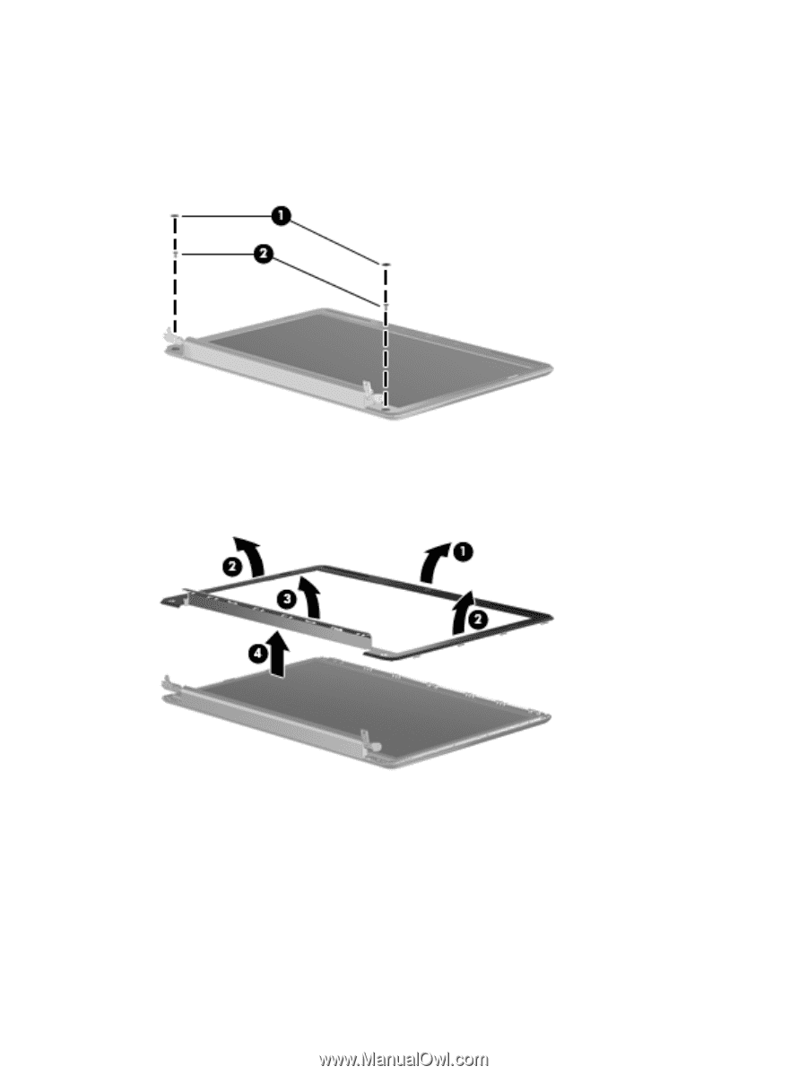
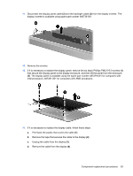
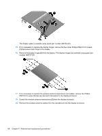
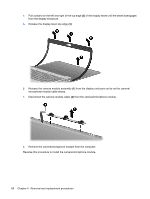
7. If it is necessary to replace any of the display assembly internal components, remove the following screw covers and screws. The display rubber screw covers are included in the Rubber Display Kit, spare part number 487283-001. (1) Two rubber screw covers on the display bezel bottom edge (2) Two Phillips PM2.5×6.0 screws 8. Flex the top side (1), the left and right sides (2), and the bottom (3) of the display bezel until the bezel disengages from the display enclosure. 9. Remove the display bezel (4). The display bezel is available using spare part number 487286-001 for computers with a camera module, 487285-001 for computers without a camera module. 10. If it is necessary to replace the inverter, release the inverter (1) from the clips in the display enclosure as far as the display panel cable and the backlight cable will allow. 62 Chapter 4 Removal and replacement procedures
-
 1
1 -
2
-
3
-
4
-
5
-
6
-
7
-
8
-
9
-
10
-
11
-
12
-
13
-
14
-
15
-
16
-
17
-
18
-
19
-
20
-
21
-
22
-
23
-
24
-
25
-
26
-
27
-
28
-
29
-
30
-
31
-
32
-
33
-
34
-
35
-
36
-
37
-
38
-
39
-
40
-
41
-
42
-
43
-
44
-
45
-
46
-
47
-
48
-
49
-
50
-
51
-
52
-
53
-
54
-
55
-
56
-
57
-
58
-
59
-
60
-
61
-
62
-
63
-
64
-
 65
65 -
 66
66 -
 67
67 -
 68
68 -
 69
69 -
 70
70 -
 71
71 -
 72
72 -
 73
73 -
 74
74 -
 75
75 -
76
-
77
-
78
-
79
-
80
-
81
-
82
-
83
-
84
-
85
-
86
-
87
-
88
-
89
-
90
-
91
-
92
-
93
-
94
-
95
-
96
-
97
-
98
-
99
-
100
-
101
-
102
-
103
-
104
-
105
-
106
-
107
-
108
-
109
-
110
-
111
-
112
-
113
-
114
-
115
-
116
-
117
-
118
-
119
-
120
-
121
-
122
-
123
-
124
-
125
-
126
-
127
-
128
-
129
-
130
-
131
-
132
-
133
-
134
-
135
-
136
-
137
-
138
-
139
-
140
-
141
-
142
-
143
-
144
-
145
-
146
-
147
-
148
-
149
-
150
-
151
-
152
-
153
-
154
-
155
 |
 |