HP ProLiant DL380p HP ProLiant DL380p Gen8 Server User Guide - Page 15
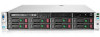
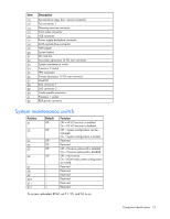
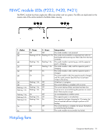
System maintenance switch, Description, Position, Default, Function
 |
View all HP ProLiant DL380p manuals
Add to My Manuals
Save this manual to your list of manuals |
Page 15 highlights
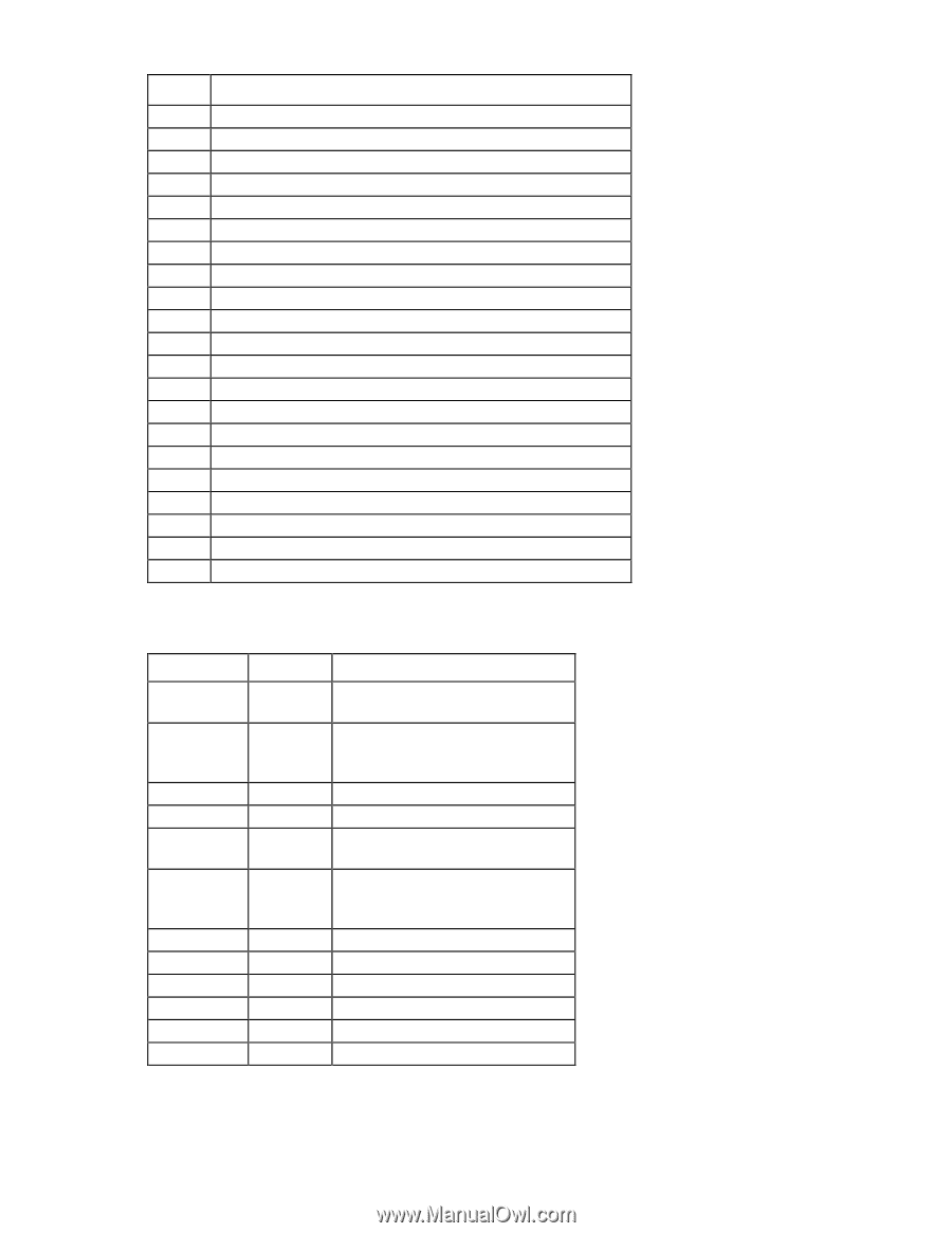
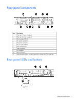
Item 12 13 14 15 16 17 18 19 20 21 22 23 24 25 26 27 28 29 30 31 32 Description Second drive cage, box 1 power connector Fan connector 1 Discovery services connector Front video connector USB connector Power supply backplane connector SATA optical drive connector NMI jumper System battery SD card slot Secondary (processor 2) PCI riser connector System maintenance switch Processor 2 socket TPM connector Primary (processor 1) PCI riser connector FlexLOM SAS connector 1 SAS connector 2 Cache module connector Processor 1 socket RDX power connector System maintenance switch Position S1 S2 S3 S4 S5 S6 S7 S8 S9 S10 S11 S12 Default Off Off Off Off Off Off - - - - - - Function Off = HP iLO security is enabled. On = HP iLO security is disabled. Off = System configuration can be changed. On = System configuration is locked. Reserved Reserved Off = Power-on password is enabled. On = Power-on password is disabled. Off = No function On = ROM reads system configuration as invalid. Reserved Reserved Reserved Reserved Reserved Reserved To access redundant ROM, set S1, S5, and S6 to on. Component identification 15
-
 1
1 -
2
-
3
-
4
-
5
-
6
-
7
-
8
-
9
-
 10
10 -
 11
11 -
 12
12 -
 13
13 -
 14
14 -
 15
15 -
 16
16 -
 17
17 -
 18
18 -
 19
19 -
 20
20 -
21
-
22
-
23
-
24
-
25
-
26
-
27
-
28
-
29
-
30
-
31
-
32
-
33
-
34
-
35
-
36
-
37
-
38
-
39
-
40
-
41
-
42
-
43
-
44
-
45
-
46
-
47
-
48
-
49
-
50
-
51
-
52
-
53
-
54
-
55
-
56
-
57
-
58
-
59
-
60
-
61
-
62
-
63
-
64
-
65
-
66
-
67
-
68
-
69
-
70
-
71
-
72
-
73
-
74
-
75
-
76
-
77
-
78
-
79
-
80
-
81
-
82
-
83
-
84
-
85
-
86
-
87
-
88
-
89
-
90
-
91
-
92
-
93
-
94
-
95
-
96
-
97
-
98
-
99
-
100
-
101
-
102
-
103
-
104
-
105
-
106
-
107
-
108
-
109
-
110
-
111
-
112
-
113
-
114
-
115
-
116
-
117
-
118
-
119
-
120
-
121
-
122
-
123
-
124
-
125
-
126
-
127
-
128
 |
 |