HP ProLiant DL380p HP ProLiant DL380p Gen8 Server User Guide - Page 88
Install the air baffle, Install the fan cage
 |
View all HP ProLiant DL380p manuals
Add to My Manuals
Save this manual to your list of manuals |
Page 88 highlights
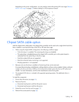
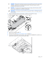
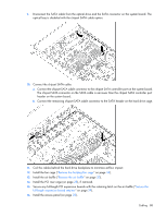
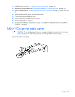
9. Disconnect the SATA cable from the optical drive and the SATA connector on the system board. The optical bay is disabled with the chipset SATA cable option. 10. Connect the chipset SATA cable: a. Connect the chipset SATA cable connector to the chipset SATA controller port on the system board. The chipset SATA connector on the SATA cable is narrower than the chipset SATA controller port header on the system board. b. Connect the remaining chipset SATA cable connector to the SATA header on the hard drive cage. 11. Coil the cables behind the hard drive backplane to minimize airflow impact. 12. Install the fan cage ("Remove the hot-plug fan cage" on page 24). 13. Install the air baffle ("Remove the air baffle" on page 30). 14. Install the PCI riser cage (on page 28), if removed. 15. Secure any full-length PCI expansion boards with the retaining latch on the air baffle ("Secure the full-length expansion board retainer" on page 29). 16. Install the access panel (on page 23). Cabling 88
-
 1
1 -
2
-
3
-
4
-
5
-
6
-
7
-
8
-
9
-
10
-
11
-
12
-
13
-
14
-
15
-
16
-
17
-
18
-
19
-
20
-
21
-
22
-
23
-
24
-
25
-
26
-
27
-
28
-
29
-
30
-
31
-
32
-
33
-
34
-
35
-
36
-
37
-
38
-
39
-
40
-
41
-
42
-
43
-
44
-
45
-
46
-
47
-
48
-
49
-
50
-
51
-
52
-
53
-
54
-
55
-
56
-
57
-
58
-
59
-
60
-
61
-
62
-
63
-
64
-
65
-
66
-
67
-
68
-
69
-
70
-
71
-
72
-
73
-
74
-
75
-
76
-
77
-
78
-
79
-
80
-
81
-
82
-
 83
83 -
 84
84 -
 85
85 -
 86
86 -
 87
87 -
 88
88 -
 89
89 -
 90
90 -
 91
91 -
 92
92 -
 93
93 -
94
-
95
-
96
-
97
-
98
-
99
-
100
-
101
-
102
-
103
-
104
-
105
-
106
-
107
-
108
-
109
-
110
-
111
-
112
-
113
-
114
-
115
-
116
-
117
-
118
-
119
-
120
-
121
-
122
-
123
-
124
-
125
-
126
-
127
-
128
 |
 |
