HP Rp7410 Site Preparation Guide, Second Edition - hp rp7405/rp7410 Servers - Page 27
Airflow Diagram
 |
View all HP Rp7410 manuals
Add to My Manuals
Save this manual to your list of manuals |
Page 27 highlights
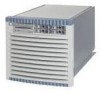
System Specifications Environmental Specifications Figure 1-1 illustrates the location of the inlet and outlet airducts on a single cabinet. Figure 1-1 Airflow Diagram Chapter 1 7
-
 1
1 -
2
-
3
-
4
-
5
-
6
-
7
-
8
-
9
-
10
-
11
-
12
-
13
-
14
-
15
-
16
-
17
-
18
-
19
-
20
-
21
-
 22
22 -
 23
23 -
 24
24 -
 25
25 -
 26
26 -
 27
27 -
 28
28 -
 29
29 -
 30
30 -
 31
31 -
 32
32 -
33
-
34
-
35
-
36
-
37
-
38
-
39
-
40
-
41
-
42
-
43
-
44
-
45
-
46
-
47
-
48
-
49
-
50
-
51
-
52
-
53
-
54
-
55
-
56
-
57
-
58
-
59
-
60
-
61
-
62
-
63
-
64
-
65
-
66
-
67
-
68
-
69
-
70
-
71
-
72
-
73
-
74
 |
 |

Chapter 1
System Specifications
Environmental Specifications
7
Figure 1-1 illustrates the location of the inlet and outlet airducts on a single cabinet.
Figure 1-1
Airflow Diagram