HP Scitex FB10000 Geffen TS Error 67022 - Page 8
Sensor calibration, Print table
 |
View all HP Scitex FB10000 manuals
Add to My Manuals
Save this manual to your list of manuals |
Page 8 highlights
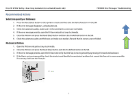
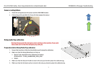
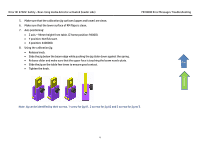
Error ID: 67022: Safety - Rear rising media detector activated (loader side) FB10000 Error Messages Troubleshooting 7. Adjust jig no'3 to the calculated height using the caliper. 8. Move X table to position 3630000 (to adjust the loader side RM). 9. Send Z axis back to 95 mm height. (Z home position-95000) 10. Push loader to rear side and go inside facing the RM. 11. Place back the jigs in the marked spots on the table (make sure the upper surface is below the flaps). 12. Place jig no'3 in the middle below the 2 flaps in the middle. 13. Release flaps screws until the flaps are leaning on the jigs top surface. 14. Tighten the flaps screws while pushing the flap against the jig surface. Raising media Top Flowchart RM JIG-1 operator RM JIG-3 Print table RM JIG-2 15. Remove the jigs. 16. Send the table to X position 5330000 (to adjust the UV side RM). 17. Go to RM UV side and place the 3 jigs in the marked spots (make sure the upper surface is below the flaps). 18. Release the flaps screws until the flaps are leaning onto the jigs top surface. 19. Tighten the flaps screws while pushing the flap against the jig surface. Sensor calibration To calibrate the sensor we will use jigs no'1 & 2. 1. Send the Z axis to the Home position. 2. Send the Z axis to 94.95 mm height from the table (Z home position-94950) Note: It is very important to go Up and then Down a few millimeters until you reach the desired location!!! 8
-
 1
1 -
2
-
 3
3 -
 4
4 -
 5
5 -
 6
6 -
 7
7 -
 8
8 -
 9
9
 |
 |
