HP T5735 Troubleshooting Guide: HP t5730 and t5735 Thin Client - Page 16
Removing and Replacing the Secure USB Compartment Cover - review
 |
UPC - 883585606238
View all HP T5735 manuals
Add to My Manuals
Save this manual to your list of manuals |
Page 16 highlights
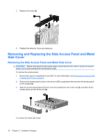
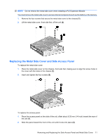
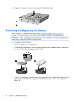
8. Replace the secure USB compartment cover. See Removing and Replacing the Secure USB Compartment Cover on page 8. 9. Reconnect any external devices and power cords. 10. Turn on the monitor, the thin client, and any devices you want to test. 11. Load any necessary drivers. NOTE: You can download select hardware drivers from HP at http://www.hp.com/country/us/eng/ support.html. 12. Reconfigure the thin client, if necessary. Removing and Replacing the Secure USB Compartment Cover The secure USB compartment allows you to install two USB devices in a secure location inside the thin client. Along with providing a hidden location, the secure USB compartment can be locked by the optional security cable lock. CAUTION: The ambient temperature inside of the secure USB compartment can reach up to 55° C (131° F) in worst case conditions. Make sure the specifications for any device you install in the compartment indicate the device can tolerate a 55° C (131° F) ambient environment. NOTE: In addition to following these instructions, follow the detailed instructions that accompany the accessory you are installing. Before beginning the installation process, review General Hardware Installation Sequence on page 7 for procedures you should follow before and after installing or replacing hardware. Removing the Secure USB Compartment Cover Use the following procedure to remove the secure USB compartment cover. WARNING! Before removing the secure USB compartment cover, ensure that the thin client is turned off and the power cord is disconnected from the electrical outlet. To remove the secure USB compartment cover: 1. Remove the antenna, if one is installed. 2. On rear of the thin client, remove the screw that secures the compartment cover to the unit (1). 3. On the front of the unit, push the compartment cover about 1.27 cm (1/2 inch) toward the back of the unit (2). 8 Chapter 2 Hardware Changes
-
 1
1 -
2
-
3
-
4
-
5
-
6
-
7
-
8
-
9
-
10
-
 11
11 -
 12
12 -
 13
13 -
 14
14 -
 15
15 -
 16
16 -
 17
17 -
 18
18 -
 19
19 -
 20
20 -
 21
21 -
22
-
23
-
24
-
25
-
26
-
27
-
28
-
29
-
30
-
31
-
32
-
33
-
34
-
35
-
36
-
37
-
38
-
39
-
40
-
41
-
42
-
43
-
44
-
45
-
46
-
47
-
48
-
49
 |
 |
