HP Vectra VL 5/xxx HP Vectra VL/VE 5/xx Series 3 PC - Familiarization Guide - Page 33
Installing Main Memory
 |
View all HP Vectra VL 5/xxx manuals
Add to My Manuals
Save this manual to your list of manuals |
Page 33 highlights
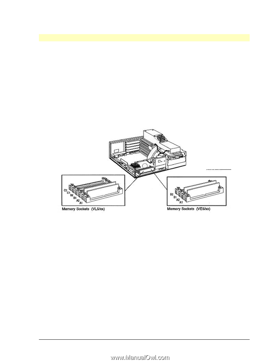
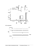
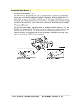
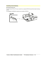
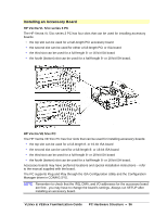
Installing Main Memory • HP Vectra VL 5/xx series 3 PC The HP Vectra VL 5/xx series 3 PC has six sockets on the system board, labeled A1, A2, B1, B2, C1, and C2 in the diagram below. Each pair of memory sockets forms a bank. Slots A1 and A2 form bank 1, slots B1 and B2 form bank 2, and slots C1 and C2 form bank 3. For the best performance, the memory modules should be installed in pairs (modules of the same size) in the same bank. A maximum of 192 MB may be installed. • HP Vectra VE 5/xx PC The HP Vectra VE 5/xx PC has four sockets on the system board, labeled A1, A2, and B1, B2 in the diagram below. Each pair of memory sockets forms a bank. Slots A1 and A2 form bank 1, and slots B1 and B2 form bank 2. For the best performance, the memory modules should be installed in pairs (modules of the same size) in the same bank. A maximum of 128 MB may be installed. VL5/xx & VE5/xx Familiarization Guide PC Hardware Structure • 33
-
 1
1 -
2
-
3
-
4
-
5
-
6
-
7
-
8
-
9
-
10
-
11
-
12
-
13
-
14
-
15
-
16
-
17
-
18
-
19
-
20
-
21
-
22
-
23
-
24
-
25
-
26
-
27
-
 28
28 -
 29
29 -
 30
30 -
 31
31 -
 32
32 -
 33
33 -
 34
34 -
 35
35 -
 36
36 -
 37
37 -
 38
38 -
39
-
40
-
41
-
42
-
43
-
44
-
45
-
46
-
47
-
48
-
49
-
50
-
51
-
52
 |
 |