HP Z620 HP Workstations - CRU Dataport DX115 kit installation - Page 15
HP Z620 Manual
 |
View all HP Z620 manuals
Add to My Manuals
Save this manual to your list of manuals |
Page 15 highlights
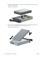
5. Install one (supplied) M3 x 5mm screw (black) for each DX115 unit for shipping support as shown. Additional M3 x 5mm screws are located on the chassis front side under the bezel. CAUTION: Failure to install the shipping screw might result in damage to the removable hard drive system. Figure 17 Installing the shipping support screw HP xw6200, HP xw6400, and HP xw6600 computers 1. 2. 3. Remove the front bezel from the computer. See Figure 14 Removing the front bezel on page 9. Remove and discard the counter-sunk shipping screw at the side of the DX115 case. See Figure 8 Removing the shipping screw on page 7. Gently slide the DX115 unit into the chassis until it locks into place, as shown in the following figure. Figure 18 Installing the DX115 case ENWW Step 2-Installing the DX115 case into the optical drive bay 11
-
 1
1 -
2
-
3
-
4
-
5
-
6
-
7
-
8
-
9
-
 10
10 -
 11
11 -
 12
12 -
 13
13 -
 14
14 -
 15
15 -
 16
16 -
 17
17 -
 18
18 -
 19
19 -
 20
20 -
21
-
22
 |
 |
