HP rp8400 Installation Guide, Third Edition - HP rp8400 Server Series
HP rp8400 Manual
 |
View all HP rp8400 manuals
Add to My Manuals
Save this manual to your list of manuals |
HP rp8400 manual content summary:
- HP rp8400 | Installation Guide, Third Edition - HP rp8400 Server Series - Page 1
Installation Guide hp rp8400 Server Series Third Edition Version 4.0 Manufacturing Part Number: A6093-96022 August 2003 USA - HP rp8400 | Installation Guide, Third Edition - HP rp8400 Server Series - Page 2
in this document is subject to change without notice. Hewlett-Packard makes no warranty of any kind with regard to this manual, including, but not limited to, the implied warranties of merchantability and fitness for a particular purpose. Hewlett-Packard shall not be held liable for errors contained - HP rp8400 | Installation Guide, Third Edition - HP rp8400 Server Series - Page 3
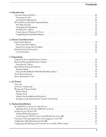
Wiring Check 51 Voltage Check 52 Voltage Check (Additional Procedure 56 Regulatory and System Serial Number Label Check 58 5. System Installation hp rp8400 Server Series AC Input Power 61 Applying Power to the hp rp8400 Server Series 63 Setting Up the CE Tool (PC 64 Setting CE Tool Parameters - HP rp8400 | Installation Guide, Third Edition - HP rp8400 Server Series - Page 4
of the Cell Boards 75 Configuring AC Line Status 76 Powering On the hp rp8400 Server Series Cabinet (48 V 77 Verifying the System Configuration 78 Adding Processors with Instant Capacity On Demand (iCOD 79 Booting HP-UX on the Partition(s 80 6. Installation Cleanup Installation Cleanup - HP rp8400 | Installation Guide, Third Edition - HP rp8400 Server Series - Page 5
Tables Table 1. Revisions 10 Table 3-1. Wheel Kit Packing List 38 Table A-1. Factory-Integrated Installation Checklist 86 5 - HP rp8400 | Installation Guide, Third Edition - HP rp8400 Server Series - Page 6
Tables 6 - HP rp8400 | Installation Guide, Third Edition - HP rp8400 Server Series - Page 7
Regulatory Label with Serial Number 58 Figure 5-1. AC Power Input Labeling 61 Figure 5-2. Distribution of Input Power for Each Bulk Power Supply 62 Figure 5-3. LAN and RS-232 Connectors on the Core I/O Board 66 Figure 5-4. Front Panel Display 67 Figure 5-5. BPS LED Location 68 Figure 5-6. MP - HP rp8400 | Installation Guide, Third Edition - HP rp8400 Server Series - Page 8
Figures 8 - HP rp8400 | Installation Guide, Third Edition - HP rp8400 Server Series - Page 9
Preface This guide provides the HP Installation Specialist with the background information and procedures needed to install the hp rp8400 server series. - HP rp8400 | Installation Guide, Third Edition - HP rp8400 Server Series - Page 10
Revision History Table 1 Revisions Edition Part Number Release Date Description Second Third A6093-96012 A6093-960 August 2002 August 2003 Updated with additions and corrections. Added Configuring a Web Console on the MP to Chapter 5. 10 - HP rp8400 | Installation Guide, Third Edition - HP rp8400 Server Series - Page 11
server series power inputs, setting up the CE Tool and configuring the MP. • Chapter 6, "Installation cleanup"-Discusses procedures to complete the cosmetic portion of the installation. • Chapter 7, "Returning equipment"-Discusses procedures to follow if equipment must be returned to Hewlett-Packard - HP rp8400 | Installation Guide, Third Edition - HP rp8400 Server Series - Page 12
12 - HP rp8400 | Installation Guide, Third Edition - HP rp8400 Server Series - Page 13
Warnings, Cautions and Notes This document presents warnings, cautions and notes in the following format. WARNING A warning highlights information that if not adhered to could cause harm or injury to personnel. CAUTION A caution highlights procedures or information necessary to avoid damage to - HP rp8400 | Installation Guide, Third Edition - HP rp8400 Server Series - Page 14
energy and, if not installed and used in accordance with the instruction manual, may cause harmful interference to radio communications. Operation of this equipment in a residential area is likely to cause harmful interference in which case the user will be required to correct the interference at - HP rp8400 | Installation Guide, Third Edition - HP rp8400 Server Series - Page 15
to the supply. WARNING This equipment is configured with multiple power sources. Hazardous voltages and energy may be present even after the removal of a single input source. Trained service personnel must follow guidelines stipulated in the service guidelines in the hp rp8400 server series EPSS - HP rp8400 | Installation Guide, Third Edition - HP rp8400 Server Series - Page 16
Bold In command syntax diagrams, italic identifies variables that must be supplied by the user. In paragraph text, bold identifies either equipment markings or actions that require an operator response. 16 - HP rp8400 | Installation Guide, Third Edition - HP rp8400 Server Series - Page 17
other documents that provide more details on the topics presented in this manual: • Standard for the Protection of Electronic Computer Data Processing Equipment 1981, Bell Laboratories • Site Preparation Guide: hp rp8400 server series • Safety and Regulatory Information: hp rp8400 server series 17 - HP rp8400 | Installation Guide, Third Edition - HP rp8400 Server Series - Page 18
18 - HP rp8400 | Installation Guide, Third Edition - HP rp8400 Server Series - Page 19
1 Introduction This chapter contains a general description of the responsibilities of the Customer and HP Installation Specialist before and during an installation. • Customer Responsibilities • HP Installation Specialist Responsibilities Chapter 1 19 - HP rp8400 | Installation Guide, Third Edition - HP rp8400 Server Series - Page 20
the Site The customer and a Hewlett-Packard representative should review the site survey and site inspection checklists located in the Site Preparation Guide: hp rp8400 server series to identify potential problems that may arise before, during, or after installation of the system. The checklists - HP rp8400 | Installation Guide, Third Edition - HP rp8400 Server Series - Page 21
Cabinet To install an hp rp8400 server, the HP Installation Specialist must connect the cables between the server and the console, and if applicable, connect modems and other peripherals. Should it become necessary to troubleshoot the server during installation or later during a service call, note - HP rp8400 | Installation Guide, Third Edition - HP rp8400 Server Series - Page 22
HP Installation Specialist Responsibilities CAUTION Do not leave side or top covers off the server for extended periods of time while troubleshooting the server. Overall reliability of the server will be compromised if covers are not replaced after servicing. Connecting and Testing AC Power - HP rp8400 | Installation Guide, Third Edition - HP rp8400 Server Series - Page 23
2 Safety Considerations It is important to observe safety procedures when installing Hewlett-Packard computers and their peripheral devices. General guidelines are provided in this chapter. • Input Power Ratings • Electrical Safety Precautions Chapter 2 23 - HP rp8400 | Installation Guide, Third Edition - HP rp8400 Server Series - Page 24
rear of the processor must be in the correct language for the installation and must show the power configuration of the power controller. Incorrect virgule (/) means that a specific voltage or frequency is required and that internal adjustments or specific component installation must be made by - HP rp8400 | Installation Guide, Third Edition - HP rp8400 Server Series - Page 25
circuit breakers are adequate for specified cabinet current loads. Refer to the Site Preparation Guide: hp rp8400 server series for circuit breaker size requirements. 4. Facility AC power connection to the processor cabinet complies with and is tested by guidelines set forth in Chapter 4, "AC - HP rp8400 | Installation Guide, Third Edition - HP rp8400 Server Series - Page 26
are present inside the server cabinet while the site AC circuit breakers are set to ON. Ensure that the site AC circuit breakers are set to OFF before servicing the system. Circuit Breakers WARNING Set all AC input circuit breakers to the OFF position before connecting a power cable plug to the - HP rp8400 | Installation Guide, Third Edition - HP rp8400 Server Series - Page 27
3 Unpacking Inspect shipping containers when the equipment arrives at the site. Check equipment after the packing has been removed. This chapter discusses how to inspect and receive the hp rp8400 server cabinet. Chapter 3 27 - HP rp8400 | Installation Guide, Third Edition - HP rp8400 Server Series - Page 28
cabinet on the customer site, and on a pallet with a wheel kit for installation as a standalone server. • "Inspecting the hp rp8400 Server Cabinet" • "Receiving the hp rp8400 Server Cabinet" • "Rack Mount System Installation" • "Wheel Kit Installation" • "Power Distribution Unit" 28 Chapter 3 - HP rp8400 | Installation Guide, Third Edition - HP rp8400 Server Series - Page 29
Inspecting the hp rp8400 Server Cabinet Hewlett-Packard shipping containers are designed to protect their contents under normal shipping conditions. After the equipment arrives at the customer site, carefully inspect each carton for signs of shipping damage. A tilt indicator is installed on each - HP rp8400 | Installation Guide, Third Edition - HP rp8400 Server Series - Page 30
Unpacking Receiving the hp rp8400 Server Cabinet Receiving the hp rp8400 Server Cabinet This section contains information pertaining to unpacking the server cabinet. WARNING Wear protective glasses while cutting the plastic bands around the shipping container. These bands are under tension. When - HP rp8400 | Installation Guide, Third Edition - HP rp8400 Server Series - Page 31
. Step 4. Remove the packing materials. Unpacking Receiving the hp rp8400 Server Cabinet CAUTION The plastic wrapping material should be cut off with each ramp secured to the pallet using two bolts. There is another configuration where the ramps are secured together on one side of the cabinet with - HP rp8400 | Installation Guide, Third Edition - HP rp8400 Server Series - Page 32
Unpacking Receiving the hp rp8400 Server Cabinet Step 6. Remove the six bolts from the base attaching rack on the casters. Use caution when rolling the cabinet off the ramp. A single server in the cabinet weighs approximately 508 pounds. It is strongly recommended that two people roll the cabinet off - HP rp8400 | Installation Guide, Third Edition - HP rp8400 Server Series - Page 33
Unpacking Receiving the hp rp8400 Server Cabinet Securing the Cabinet Once in position, secure and stabilize the cabinet using the leveling feet at the corners of the base and install the anti-tip mechanisms on the bottom front and rear of the rack. Figure 3-4 Securing the Cabinet Chapter 3 33 - HP rp8400 | Installation Guide, Third Edition - HP rp8400 Server Series - Page 34
of the hardware and tools required to perform the installation of the products mentioned. Installation of the products is illustrated in this guide. The part number for this installation guide is J1528-90001. Manual Lifting Use this procedure only if no Hewlett-Packard approved lift is available - HP rp8400 | Installation Guide, Third Edition - HP rp8400 Server Series - Page 35
/web_docs/C03-0010.pdf Step 3. Unfold the handles so they are extended out from the unit. The server is now ready for manual lifting by the FOUR (4) qualified HP Service Personnel. Step 4. After the server is secured, re-install the previously removed Cell Boards and Bulk Power Supplies. Using the - HP rp8400 | Installation Guide, Third Edition - HP rp8400 Server Series - Page 36
Rack Mount System Installation • Installing the ballast kit (J1479A) • Installing the barrel nuts on the front and rear columns • Installing the slides Step 2. Follow the instructions on the outside of the server packaging to remove the banding and carton top from the server pallet. Step 3. Insert - HP rp8400 | Installation Guide, Third Edition - HP rp8400 Server Series - Page 37
moving it over to the rack. Step 7. Follow the HP J1528A Rack Integration Kit Installation Guide to complete these steps: • Mounting the server to the slides • Installing the cable management arm (CMA) • Installing the interlock device assembly (if two servers are in the same cabinet) Chapter 3 37 - HP rp8400 | Installation Guide, Third Edition - HP rp8400 Server Series - Page 38
wheel kit before beginning the installation. Table 3-1 Wheel Kit Packing List Part Number A6093-04081 A6093-04082 A6093- 1 1 8 1 2 Tools Required for Installation The following list provides the installer with the recommended tools to perform the wheel kit installation. • Diagonal side cutters • - HP rp8400 | Installation Guide, Third Edition - HP rp8400 Server Series - Page 39
polystrap bands securing the HP Server to the pallet. 2. Lift the carton top from the cardboard tray resting on the pallet. 3. Remove the bezel kit carton and top cushion from the pallet. Figure 3-7 Bezel Kit and Top Cushion Top Cushions Unpacking Wheel Kit Installation Bezel Kit Pallet 4. Unfold - HP rp8400 | Installation Guide, Third Edition - HP rp8400 Server Series - Page 40
Unpacking Wheel Kit Installation 5. Remove the front cushion only. Do not remove any other cushions until further instructed. Figure 3-8 Removal of Cushion from Front Edge of Server Rear Cushion Side Cushion Front Cushion 6. Open the wheel kit box and locate the two front casters. The front - HP rp8400 | Installation Guide, Third Edition - HP rp8400 Server Series - Page 41
Unpacking Wheel Kit Installation 7. Remove two of the eight screws from the plastic pouch. Attach one wheel caster to the front of the server. Figure 3-9 Attaching a Caster Wheel to the Server Front Caster 8. Attach the remaining front caster to the server using two more screws supplied in the - HP rp8400 | Installation Guide, Third Edition - HP rp8400 Server Series - Page 42
Unpacking Wheel Kit Installation 12. Attach the ramp to the edge of the pallet. Note there are two pre-drilled holes in the ramp. Use the two screws taped to the ramp and attach it to the pallet. Figure 3-10 Attaching the Ramp to the Pallet Positioning the Screw in the Ramp 42 Chapter 3 - HP rp8400 | Installation Guide, Third Edition - HP rp8400 Server Series - Page 43
Unpacking Wheel Kit Installation 13. Remove the two side cushions from the server and unfold the cardboard tray so that it lays flat on the pallet. Figure 3-11 Side Cushion Removal from Server Side Cushion Ramp 14. Carefully roll the server off the pallet and down the ramp. 15. Obtain the - HP rp8400 | Installation Guide, Third Edition - HP rp8400 Server Series - Page 44
Unpacking Wheel Kit Installation 16. Insert the slot on the pedestal cover into the front caster. Secure the pedestal cover to the server by tightening the captive screw on the cover at the rear of the server. Figure 3-12 Securing each Pedestal Cover to the Server Rear Caster Pedestal Covers Front - HP rp8400 | Installation Guide, Third Edition - HP rp8400 Server Series - Page 45
Unpacking Wheel Kit Installation 17. Wheel kit installation is complete once both pedestal covers are attached to the server and the bezel cover is snapped into place on the front of the server. Figure 3-13 Completed Wheel Kit Installation Attached Pedestal Cover Chapter 3 45 - HP rp8400 | Installation Guide, Third Edition - HP rp8400 Server Series - Page 46
Web site at http://www.hp.com/racksolutions. The internal Web site is http://racksolutions.corp.hp.com. The 60A PDU installation guide will contain • PDU Contents • Hardware • Tools required • Installation diagrams with text The part number for this installation guide is 5969-6523. 46 Chapter - HP rp8400 | Installation Guide, Third Edition - HP rp8400 Server Series - Page 47
4 AC Power Once the system has been unpacked and moved into position, it must be connected to a source of AC power which must be checked before the system is powered up. This chapter describes these activities. • Overview • AC Power Connections Chapter 4 47 - HP rp8400 | Installation Guide, Third Edition - HP rp8400 Server Series - Page 48
AC Power • Wiring and Voltage Checks 48 Chapter 4 - HP rp8400 | Installation Guide, Third Edition - HP rp8400 Server Series - Page 49
The hp rp8400 server series has an AC power plug on a 3-wire AC power cable. These systems connect to a power source of 200-240 V AC. WARNING Do not set site AC circuit breakers serving the cabinet(s) to ON before verifying that the cabinet has been wired into the site AC power supply correctly - HP rp8400 | Installation Guide, Third Edition - HP rp8400 Server Series - Page 50
attaching the site AC power to the server cabinet. See the Site Preparation Guide for the hp rp8400 Server Series for a more detailed explanation. Hewlett-Packard personnel should not be directly involved in the selection of material, installation, or connection of site AC power. In all cases, this - HP rp8400 | Installation Guide, Third Edition - HP rp8400 Server Series - Page 51
incorrectly wired into the site AC power supply. Always verify correct wiring and cabinet grounding before applying AC power to the cabinet. Failure to do green power cord safety ground to the site ground point. This is accomplished through the power cord receptacle wiring. When required, cabinets - HP rp8400 | Installation Guide, Third Edition - HP rp8400 Server Series - Page 52
to the site AC power supply ground: Step 1. Ensure that the site AC power supply circuit breakers serving the power cord plug end specified as an IEC 320 C19 type plug. This is the end that plugs directly into the back of the server cabinet. NOTE These procedures need to be performed for each power - HP rp8400 | Installation Guide, Third Edition - HP rp8400 Server Series - Page 53
AC Power Wiring and Voltage Checks Voltage Range Verification of Receptacle This L1 and ground. In North America, verify this voltage is between 100 120 volts AC. In Europe and certain parts of Asia-Pacific, verify this voltage is between 200 - 240 volts AC. Step 3. Measure the voltage between L2 - HP rp8400 | Installation Guide, Third Edition - HP rp8400 Server Series - Page 54
that the measurement is between 0 - 5 volts AC. If the measurement is 5V or greater, escalate the situation. Do not attempt to plug the power cords into the server cabinet. Step 2. Measure the voltage between B0 and B1. Take the AC voltage down to the lowest scale on the volt meter. One probe - HP rp8400 | Installation Guide, Third Edition - HP rp8400 Server Series - Page 55
that the measurement is between 0 - 5 volts AC. If the measurement is 5V or greater, escalate the situation. Do not attempt to plug the power cords into the server cabinet. Step 2. Measure the voltage between B0 and B1. Take the AC voltage down to the lowest scale on the volt meter. One probe - HP rp8400 | Installation Guide, Third Edition - HP rp8400 Server Series - Page 56
server and to check the UPS output voltage. UPS User Manual documentation is shipped with the UPS. Documentation may also be found at http://hpcp.grenoble.hp.com Step 1. Verify that site power processor cabinet(s) to ON before verifying that the cabinet has been wired into the site AC power supply - HP rp8400 | Installation Guide, Third Edition - HP rp8400 Server Series - Page 57
WARNING SHOCK HAZARD Risk of shock hazard while testing primary power. Use properly insulated probes. Be sure to replace access cover when finished testing primary power. Step 10. Set the server power to ON. Step 11. Check that the indicator light on each power supply is lit. Chapter 4 57 - HP rp8400 | Installation Guide, Third Edition - HP rp8400 Server Series - Page 58
label affixed to cabinet. This label is printed in the appropriate language for the installation location. The serial number check verifies that the label is affixed to the server and that it is printed in the correct language. Refer to Figure 4-5 for label details. Figure 4-5 Regulatory - HP rp8400 | Installation Guide, Third Edition - HP rp8400 Server Series - Page 59
5 System Installation This chapter contains the procedures for completing the system installation procedures for the hp rp8400 server series. • "hp rp8400 Server Series AC Input Power" • "Setting Up the CE Tool (PC)" Chapter 5 59 - HP rp8400 | Installation Guide, Third Edition - HP rp8400 Server Series - Page 60
System Installation • "Turning On Housekeeping Power and Logging in to the MP" • "Configuring LAN Information for the MP" • "Configuring the Management Processor for use with a Web Console" • "Verifying Presence of the Cell Boards" • "Configuring AC Line Status" • "Powering On the hp rp8400 Server - HP rp8400 | Installation Guide, Third Edition - HP rp8400 Server Series - Page 61
System Installation hp rp8400 Server Series AC Input Power hp rp8400 Server Series AC Input Power The server can receive AC input from two different AC power sources. If two separate power sources are available, the server can be plugged into the separate power sources increasing system reliability - HP rp8400 | Installation Guide, Third Edition - HP rp8400 Server Series - Page 62
BPS installed exceeds the number of cell boards installed by one BPS. • An additional BPS is required for each additional cell board installed in the server. For the case where two cell boards are installed, there would be a total of four BPS needed to support the two cell board configuration while - HP rp8400 | Installation Guide, Third Edition - HP rp8400 Server Series - Page 63
System Installation hp rp8400 Server Series AC Input Power Applying Power to the hp rp8400 Server Series Initial observations can be made as to the functionality of the server before attaching any LAN or serial cables, the system console or any peripherals to the server. When an active AC power - HP rp8400 | Installation Guide, Third Edition - HP rp8400 Server Series - Page 64
server. The MP monitors the activity of either a one partition or a multiple partition configuration. During installation, communicating with the MP enables such tasks as: • Verifying that the components are present and installed correctly • Setting LAN IP addresses • Shutting down cell board power - HP rp8400 | Installation Guide, Third Edition - HP rp8400 Server Series - Page 65
the following procedure: 1. From the Reflection 1 Main screen, pull down the Connection menu and select Connection Setup. 2. Select Serial Port. 3. Select Com1. 4. Check the settings and change, if required. Go to More Settings to set Xon/Xoff. Click OK to close the More Settings window. 5. Click OK - HP rp8400 | Installation Guide, Third Edition - HP rp8400 Server Series - Page 66
System Installation Setting Up the CE Tool (PC) 1. Connect one end of a null modem cable (9-pin to 9-pin) (Part Number 5182-4794) to the Local RS-232 port on the Core I/O card (the DB9 connector located at the bottom of the Core I/O card). Figure 5-3 LAN and RS-232 Connectors on the Core I/O Board - HP rp8400 | Installation Guide, Third Edition - HP rp8400 Server Series - Page 67
Bulk Power Supplies (BPS) located at the front of the server cabinet, which in turn provides housekeeping power (HKP). Before powering up the server cabinet for the first time: 1. Verify that the AC voltage at the input source is within specifications for each server cabinet being installed. 2. If - HP rp8400 | Installation Guide, Third Edition - HP rp8400 Server Series - Page 68
System Installation Turning On Housekeeping Power and Logging in to the MP • after 30 seconds has elapsed. Note the flashing amber BPS LED for each BPS becomes a flashing green LED Figure 5-5 BPS LED Location 3. Login to the MP: a. Enter Admin at the login prompt. (This term is case sensitive.) It - HP rp8400 | Installation Guide, Third Edition - HP rp8400 Server Series - Page 69
The MP Main Menu appears: Figure 5-6 MP Main Menu System Installation Turning On Housekeeping Power and Logging in to the MP MP login: Admin MP password: Welcome to the S Class 16K-A Management Processor (c) Copyright 1995-2001 Hewlett-Packard Co., All Rights Reserved. Version 0.23 MP MAIN MENU: - HP rp8400 | Installation Guide, Third Edition - HP rp8400 Server Series - Page 70
the MP Command Menu prompt (MP:CM>), enter lc (for LAN configuration). The screen displays the default values and asks if you want to modify them. It is a good idea to write down the information, as it may be required for future troubleshooting. NOTE If the Command Menu is not shown, enter q to - HP rp8400 | Installation Guide, Third Edition - HP rp8400 Server Series - Page 71
System Installation Configuring LAN Information for the MP 5. Confirm the new address. 6. Enter come from the customer. 8. Once step 7 is completed, the system will indicate the parameters have been updated and return to the MP Command Menu prompt (MP:CM>) 9. To check the LAN parameters and status, - HP rp8400 | Installation Guide, Third Edition - HP rp8400 Server Series - Page 72
System Installation Configuring the Management Processor for use with a Web Console Configuring the Management Processor for use with a Web Console The Web console is an embedded feature of the management processor (MP). The Web console allows access to the server via the LAN port on the core I/O - HP rp8400 | Installation Guide, Third Edition - HP rp8400 Server Series - Page 73
System Installation Configuring the Management Processor for use part of the MP employs the same users as the MP. Step 5. Set configurable parameters. Adding Users - The MP provides a maximum of 20 users. Only the MP administrator can add or remove users or change the MP configuration. To add a user - HP rp8400 | Installation Guide, Third Edition - HP rp8400 Server Series - Page 74
System Installation Configuring the Management Processor for use with a Web Console Removing Users - Users can be removed or disabled with the security options command. To remove a user, perform the following: 1. Access the MP. 2. Enter the Security Options and access control (so) command. 3. Select - HP rp8400 | Installation Guide, Third Edition - HP rp8400 Server Series - Page 75
of the Cell Boards To perform this activity, either connect to the Management Processor (MP) over the customer console or connect the CE Tool (laptop) to the RS-232 Local port on the MP. After login to the MP, verify that the MP detects the presence of all the cells installed in the server cabinet - HP rp8400 | Installation Guide, Third Edition - HP rp8400 Server Series - Page 76
is applied to each of the AC input cords for the server. This is achieved by sampling the status of the bulk power supplies. During installation, use the following procedure to check the configuration for the AC line status and configure it to match the customer's environment. Step 1. At the MP - HP rp8400 | Installation Guide, Third Edition - HP rp8400 Server Series - Page 77
System Installation Powering On the hp rp8400 Server Series Cabinet (48 V) Powering On the hp rp8400 Server Series Cabinet (48 V) After powering on the Management Processor (MP) (+3.3 V HKP), and checking that the MP detects the presence of the cell boards, power up the server cabinet, or, apply - HP rp8400 | Installation Guide, Third Edition - HP rp8400 Server Series - Page 78
Verifying the System Configuration At this point in the installation process, the hardware is set up, the Management Processor (MP) is connected to the LAN, the AC and DC power have been turned on, and the selftest is completed. Now the configuration can be verified. After DC is powered on and the - HP rp8400 | Installation Guide, Third Edition - HP rp8400 Server Series - Page 79
system, but they belong to Hewlett-Packard (HP) and therefore are HP assets. A nominal "Right-To-Access Fee" is paid to HP for each iCOD processor in the system. At any time, any number of iCOD CPUs can be "activated." Activating an iCOD CPU automatically and instantaneously transforms the iCOD - HP rp8400 | Installation Guide, Third Edition - HP rp8400 Server Series - Page 80
System Installation Booting HP-UX on the Partition(s) Booting HP-UX on the Partition(s) To boot HP-UX on a partition: 1. At the MP Main Menu, enter co. If at the BCH prompt, enter Ctrl B to return to the MP Main Menu. If - HP rp8400 | Installation Guide, Third Edition - HP rp8400 Server Series - Page 81
6 Installation Cleanup After the hp rp8400 server series has been installed in a computer room and verified, conduct the post installation check. Before turning the system over to the customer, it is important to inspect the system visually and clean up the installation area. Chapter 6 81 - HP rp8400 | Installation Guide, Third Edition - HP rp8400 Server Series - Page 82
parts, tools, and other items used to install installation and cleanup, we recommend that you make the appropriate notations in the Gold Book, which should have been shipped with the system. • Obtain customer acceptance (if required). This includes thanking the customer for choosing Hewlett-Packard - HP rp8400 | Installation Guide, Third Edition - HP rp8400 Server Series - Page 83
7 Returning Equipment If damaged equipment is found, use the following procedure to return it to Hewlett-Packard. Chapter 7 83 - HP rp8400 | Installation Guide, Third Edition - HP rp8400 Server Series - Page 84
service to be performed. Include the SPU cabinet model number. To repackage the SPU cabinet, follow the repackage checklist below and refer to the unpacking instructions for details. Step 1. Assemble the original HP packing materials, or contact your local Hewlett-Packard Sales and Support office - HP rp8400 | Installation Guide, Third Edition - HP rp8400 Server Series - Page 85
A Installation Checklist This section provides a means of tracking progress to ensure that all steps required for a successful installation are completed. Appendix A 85 - HP rp8400 | Installation Guide, Third Edition - HP rp8400 Server Series - Page 86
installation aid and should be used only after you have installed a few systems using the detailed procedures described in the body of this manual. Integrated Installation Checklist PROCEDURE Initials Obtain LAN information Verify site preparation Site grounding verified Power requirements verified - HP rp8400 | Installation Guide, Third Edition - HP rp8400 Server Series - Page 87
for proper installation Set up CE tool and connect to Remote RS-232 port on MP Apply power to cabinet (Housekeeping) Check power to BPSs Log in to MP Set LAN IP address on MP Connect customer console Set up network on customer console Verify LAN connection Verify presence of cells Power on cabinet - HP rp8400 | Installation Guide, Third Edition - HP rp8400 Server Series - Page 88
) Perform visual inspection and complete installation Set up network services (if required) Enable iCOD (if available) Final inspection of circuit boards Final inspection of cabling Area cleaned and debris and packing materials disposed of Tools accounted for Parts and other items disposed of Make - HP rp8400 | Installation Guide, Third Edition - HP rp8400 Server Series - Page 89
B Accessing the MP Using a Modem A modem may be used to access the Management Processor (MP) remotely. A modem is often used in conjunction with a paging device to alert a remote monitor about the condition of the SPU. As with the Local - HP rp8400 | Installation Guide, Third Edition - HP rp8400 Server Series - Page 90
connect one end of a modem cable to the Remote RS-232 port on the Core I/O card. Figure B-1 Remote Connection 2. Connect the other end of the RS-232 cable to the modem. 3. Connect a dedicated phone (analog) line to the modem. 4. Set modem configuration as specified for remote support. 90 Appendix - HP rp8400 | Installation Guide, Third Edition - HP rp8400 Server Series - Page 91
Accessing the MP Using a Modem To modify the modem configuration to configure remote login, enter ca (Configure Asynchronous and Modem Parameters) at the MP command prompt (MP:CM>) and follow the instruction on the screen. Figure B-2 The ca Command Screen MP> cm Enter HE to get a list of - HP rp8400 | Installation Guide, Third Edition - HP rp8400 Server Series - Page 92
from the customer. 2. Contact the testing organization. This could be the Response Center or the WWSIT team. 3. Provide the organization with the phone number and parameters set using the MP ca command. 4. Request confirmation of the communication link, or check the modem light for activity. 92 - HP rp8400 | Installation Guide, Third Edition - HP rp8400 Server Series - Page 93
77 bo (Boot) command, 80 booting HP-UX, 80 BPS (Bulk Power Supply), 67 Bulk Power Supplies BPS, 62 C ca (Configure Asychronous and Modem Parameters) command, 91 cables, checking, 82 cell board, 62 verifying presence, 75 checklist installation, 86 circuit boards, checking, 82 circuit breakers, 26 cm - HP rp8400 | Installation Guide, Third Edition - HP rp8400 Server Series - Page 94
(MP), 64 ME (Memory) command, 78 modem, 89 MP login name, 68 password, 68 MP (Management Processor) logging in, 67 powering on, 67 MP network name, 70 N N+1 capability, 62 notational conventions, 15 notes and cautions, 13 null modem cable connectivity, 65 part number, 65 P password MP, 68 PDC
-
 1
1 -
 2
2 -
 3
3 -
 4
4 -
 5
5 -
 6
6 -
 7
7 -
8
-
9
-
10
-
11
-
12
-
13
-
14
-
15
-
16
-
17
-
18
-
19
-
20
-
21
-
22
-
23
-
24
-
25
-
26
-
27
-
28
-
29
-
30
-
31
-
32
-
33
-
34
-
35
-
36
-
37
-
38
-
39
-
40
-
41
-
42
-
43
-
44
-
45
-
46
-
47
-
48
-
49
-
50
-
51
-
52
-
53
-
54
-
55
-
56
-
57
-
58
-
59
-
60
-
61
-
62
-
63
-
64
-
65
-
66
-
67
-
68
-
69
-
70
-
71
-
72
-
73
-
74
-
75
-
76
-
77
-
78
-
79
-
80
-
81
-
82
-
83
-
84
-
85
-
86
-
87
-
88
-
89
-
90
-
91
-
92
-
93
-
94
 |
 |

Installation Guide
hp rp8400 Server Series
Third Edition
Version 4.0
Manufacturing Part Number: A6093-96022
August 2003
USA