HP t5400 Troubleshooting Guide: HP t5400 Thin Client - Page 23
Serial Port Jumper Locations on the System Board, on Serial, CAUTION
 |
View all HP t5400 manuals
Add to My Manuals
Save this manual to your list of manuals |
Page 23 highlights
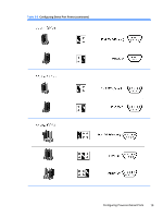
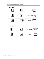
Table 2-2 COM Port Functionality (continued) pin # COM1 (Standard) COM2-Cable Connection (Customized) COM3 (Customized) pin 8 CTS RXD/TXD/RXD (TTL)/ CTS TXD (TTL) pin 9 RI TXD/RXD/TXD (TTL)/ RI RXD (TTL) COM4 (Customized) CTS RI CAUTION: To prevent severe equipment damage, carefully verify the location of the COM Port Jumper before you configure it. See Figure 2-4 Serial Port Jumper Locations on the System Board on page 13 for locations. NOTE: The jumpers in the following table are in the same orientation illustrated in Figure 2-4 Serial Port Jumper Locations on the System Board on page 13. Table 2-3 Configuring Serial Port Power Configuring Powered Serial Ports 15
-
 1
1 -
2
-
3
-
4
-
5
-
6
-
7
-
8
-
9
-
10
-
11
-
12
-
13
-
14
-
15
-
16
-
17
-
 18
18 -
 19
19 -
 20
20 -
 21
21 -
 22
22 -
 23
23 -
 24
24 -
 25
25 -
 26
26 -
 27
27 -
 28
28 -
29
-
30
-
31
-
32
-
33
-
34
-
35
-
36
-
37
-
38
-
39
-
40
-
41
-
42
-
43
-
44
-
45
-
46
-
47
-
48
-
49
-
50
-
51
-
52
-
53
-
54
-
55
-
56
-
57
-
58
-
59
-
60
-
61
-
62
-
63
-
64
-
65
-
66
-
67
-
68
-
69
-
70
-
71
-
72
-
73
-
74
-
75
-
76
 |
 |

Table 2-2
COM Port Functionality (continued)
pin #
COM1
(Standard)
COM2–Cable
Connection
(Customized)
COM3
(Customized)
COM4
(Customized)
pin 8
CTS
RXD/TXD/RXD (TTL)/
TXD (TTL)
CTS
CTS
pin 9
RI
TXD/RXD/TXD (TTL)/
RXD (TTL)
RI
RI
CAUTION:
To prevent severe equipment damage, carefully verify the location of the COM Port
Jumper before you configure it. See
Figure
2
-
4
Serial Port Jumper Locations on the System Board
on page
13
for locations.
NOTE:
The jumpers in the following table are in the same orientation illustrated in
Figure
2
-
4
Serial
Port Jumper Locations on the System Board
on page
13
.
Table 2-3
Configuring Serial Port Power
Configuring Powered Serial Ports
15