Honeywell CT2800 Owner's Manual - Page 5
Step 3. Install Mounting Plate
 |
View all Honeywell CT2800 manuals
Add to My Manuals
Save this manual to your list of manuals |
Page 5 highlights
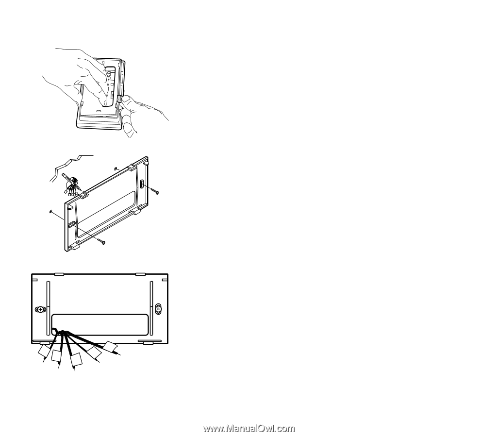
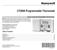
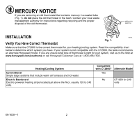
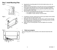
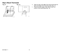
Step 3. Install Mounting Plate Fig. 5. M20139 Fig. 6. a. Separate the mounting plate from the thermostat using a coin, as shown in Fig 5. b. Position the mounting plate on the wall. Be sure the mounting plate is flush against the wall and none of the wires are trapped behind it. c. Level the mounting plate and use a pencil to mark the center of the mounting plate screw holes. d. Remove the mounting plate and drill holes at the locations marked. • For drywall, drill two 3/16-inch holes. • For plaster or wood, drill two 7/32-inch holes. e. If installing in drywall, gently tap the anchors (provided) into the drilled holes until they are flush with the wall. f. Reposition the mounting plate over the holes, pull the wires through the wiring opening, and loosely insert the mounting screws into each of the drilled holes or anchors (Fig. 6). g. Make sure the mounting plate is level and tighten the mounting screws. Fig. 7. M20129 ✓ Check your progress The mounting plate is now mounted on the wall and should look like Fig. 7. Y G Rc RW M20128 5 69-1638-1
-
 1
1 -
 2
2 -
 3
3 -
 4
4 -
 5
5 -
 6
6 -
 7
7 -
 8
8 -
 9
9 -
 10
10 -
 11
11 -
12
-
13
-
14
-
15
-
16
-
17
-
18
-
19
-
20
-
21
-
22
-
23
-
24
 |
 |