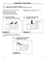
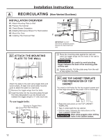
Hotpoint RVM5160MPSA Installation Instructions - Page 10
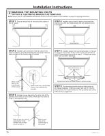
Step 2, Step 1, Step 4, Step 5, Step 6, Option 2: Use Metal Bracket As Template, Step 3
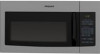 |
View all Hotpoint RVM5160MPSA manuals
Add to My Manuals
Save this manual to your list of manuals |
Page 10 highlights
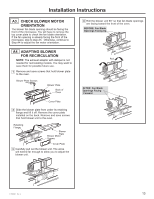
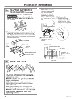
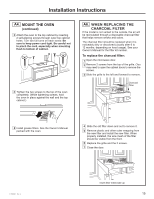
Installation Instructions D MARKING THE MOUNTING HOLES OPTION 2: USE METAL BRACKET AS TEMPLATE NOTE: Refer to step C "DETERMINING MOUNTING PLATE LOCATION UNDER YOUR CABINET on page 8 for aligning instructions. STEP 1: Draw a vertical line on the wall at the center of the 30" space. STEP 4: Installer uses a level to draw a horizontal line that connects the two marks made with the stamped slot in the bracket. Horizontal line STEP 2: Installer uses bracket to make 2 marks. First mark is made by using the stampled slot in bracket. Second mark is made on the ouside edge of bracket. STEP 5: Installer places the mounting bracket on the wall as shown in the picture. Draw circles on the wall at holes A and B. Draw at least one circle in area C. At least one circle MUST line up with a wall stud. Mark hole locations for A, B, and area C. A C B Make a mark here on the outside edge of the bracket Make a mark here, along inside bottom of the stamped slot provided. STEP 3: Installer moves bracket to the other side of the cabinets and makes 2 more marks. Marks are the same as STEP 2, just opposite side. Place bracket within the lines created in previous steps. STEP 6: Set mounting bracket aside and drill holes at all marked locations. If there is a stud, drill a 3/16" hole for wood screws. For holes that do not line up with a stud, drill a 5/8" hole for a toggle bolt. Make a mark here, along inside bottom of the stamped slot provided (same as Step 1). 10 Make a mark here on the outside edge of the bracket 31-7000091 Rev. 2
-
 1
1 -
2
-
3
-
4
-
 5
5 -
 6
6 -
 7
7 -
 8
8 -
 9
9 -
 10
10 -
 11
11 -
 12
12 -
 13
13 -
 14
14 -
 15
15 -
16
-
17
-
18
-
19
-
20
-
21
-
22
-
23
-
24
-
25
-
26
-
27
-
28
-
29
-
30
-
31
-
32
-
33
-
34
-
35
-
36
-
37
-
38
-
39
-
40
-
41
-
42
-
43
-
44
-
45
-
46
-
47
-
48
 |
 |
