Hunter 42177 Owner's Manual
Hunter 42177 Manual
 |
View all Hunter 42177 manuals
Add to My Manuals
Save this manual to your list of manuals |
Hunter 42177 manual content summary:
- Hunter 42177 | Owner's Manual - Page 1
English Owner's Manual Model 42177W Form# 44043-01 20100219 ©2010 Hunter Fan Co. - Hunter 42177 | Owner's Manual - Page 2
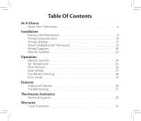
22 Operation Selector Switches 24 Set Temperature 25 Filter Monitor 26 Span Setting 27 Low Battery Warning 28 Error Mode 29 Features Additional Features 30 Troubleshooting 31 Thermostat Assistance Technical Support 33 Warranty 1 year Guarantee 34 - Hunter 42177 | Owner's Manual - Page 3
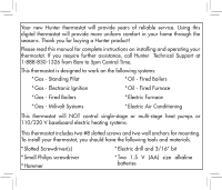
new Hunter thermostat will provide years of reliable service. Using this digital thermostat will provide more uniform comfort in your home through the seasons. Thank you for buying a Hunter product! Please read this manual for complete instructions on installing and operating your thermostat. If - Hunter 42177 | Owner's Manual - Page 4
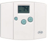
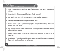
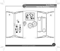
1 1. Reset: Press with a paper clip to reset the thermostat and return to power-up settings. 2. System Switch: Selector switch for Heat, Cool, and Off. 3. Fan Switch: Fan switch for Automatic or Continuous fan operation.. 4. - Hunter 42177 | Owner's Manual - Page 5
1 At A Glance Know Your Thermostat 8 1 6 8 7 23 4 5 ©2010 Hunter Fan Company 5 - Hunter 42177 | Owner's Manual - Page 6
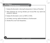
. 2. When displayed, this warning indicates your furnace filter may need to be checked or replaced. 3. Displays the thermostat is set to run HEAT or COOL. 4. Low battery warning, replace the batteries in the thermostat. 5. Indicates the current room temperature. 6 44043-01 • 02/19/2010 - Hunter 42177 | Owner's Manual - Page 7
1 At A Glance Know Your Thermostat 1 2 5 4 3 ©2010 Hunter Fan Company 7 - Hunter 42177 | Owner's Manual - Page 8
wiring from existing thermostat before reading the instructions carefully. Wires must be labeled prior to removal. IMPORTANT! Turn off the power to the furnace at the main power panel or at the furnace. Remove existing thermostat cover and thermostat. See Figure 1. Some thermostats will have screws - Hunter 42177 | Owner's Manual - Page 9
2 Installation Remove Old Thermostat RC Y G W Wallplate Thermostat Cover RC Y G W Wallplate Figure 1. Thermostat ©2010 Hunter Fan Company Cover 9 - Hunter 42177 | Owner's Manual - Page 10
. This will allow you to keep a record of your old thermostat's wiring configuration should you need to refer to it at a later time. This will also help our Technical Support Department determine your system type and proper wiring, should you need to contact them. Wire color does not indicate - Hunter 42177 | Owner's Manual - Page 11
2 Wire Color Installation Wiring Documentation Wire Letter Table A. ©2010 Hunter Fan Company 11 - Hunter 42177 | Owner's Manual - Page 12
. If the hole in wall is larger than necessary for wires, seal this hole with insulating material so that no hot or cold air can enter the back of the thermostat from the wall. This air could cause a false thermostat reading. Warning: Do not connect a "Common" wire (sometimes labeled "C") to any - Hunter 42177 | Owner's Manual - Page 13
on your then mark the wire existing thermostat is with label shown RH, R, VR or 4 24 Volt RC, VC 24 Volt Cool G or F Fan Installation Wiring Labeling and connect to thermostat terminal shown x x x Y, C or M x Air Conditioning Compressor W or H Heating Table B. ©2010 Hunter Fan Company x 13 - Hunter 42177 | Owner's Manual - Page 14
Installation Mount Wallplate and Thermostat 2 Remove the wallplate from your thermostat by pressing the release tab on the bottom of the thermostat. 14 44043-01 • 02/19/2010 - Hunter 42177 | Owner's Manual - Page 15
2 Installation Mount Wallplate and Thermostat Figure 2. ©2010 Hunter Fan Company 15 - Hunter 42177 | Owner's Manual - Page 16
Installation Mount Wallplate and Thermostat 2 1. Position wallplate on wall and pull existing wires through large opening. Then level for appearance. Mark holes for plastic anchors provided, if your existing holes - Hunter 42177 | Owner's Manual - Page 17
2 Installation Mount Wallplate and Thermostat Figure 3. ©2010 Hunter Fan Company 17 - Hunter 42177 | Owner's Manual - Page 18
* Be sure to tighten the terminal screws securely, otherwise a loose wire could cause operational problems with your system or thermostat. * Push excess wire back into the hole to prevent interference when installing the thermostat to the wallplate. * Make sure the System Switch is set to OFF, and - Hunter 42177 | Owner's Manual - Page 19
2 Installation Mount Wallplate and Thermostat Figure 4. ©2010 Hunter Fan Company 19 - Hunter 42177 | Owner's Manual - Page 20
Installation Wiring Diagrams 2 Wallplate Terminals 4-wire Heat/Cool System Jumper Fan Relay Heat Relay Cool or Valve Contactor Heat/Cool 24V Supply Wallplate Terminals 5-wire Heat/Cool System No Jumper Fan Relay Heat Relay or Valve Cool contactor Heat 24V Supply Cool 24V Supply 20 - Hunter 42177 | Owner's Manual - Page 21
2 Installation Wiring Diagrams 3-wire Heat Only System Wallplate Terminals Jumper Fan Relay Heat Relay or Valve Heat 24V Supply Wallplate Terminals 2-wire Heat Only System Jumper Heat Relay or Valve Heat 24V or Millivolt Supply ©2010 Hunter Fan Company 21 - Hunter 42177 | Owner's Manual - Page 22
after installation. If the Fan operation is normal, leave it in the "HG" position. If the Fan does not come on within a minute of the thermostat calling for heat, change the switch position to "HE". The system selector has no effect in the cooling mode. NOTE: "HG" position is for gas - Hunter 42177 | Owner's Manual - Page 23
2 Installation Selector Switches ON DIP 1 234 (SW4) A0 1 A1 A2 A3 (SW5) 2 Figure 5. ©2010 Hunter Fan Company 23 - Hunter 42177 | Owner's Manual - Page 24
Operation Selector Switches 3 The System Selector switch on the front of the thermostat determines the operating mode of the thermostat. You may select COOL, OFF, HEAT. NOTE: Anytime you install or remove the thermostat from the wallplate, slide the System Selector to the OFF position to prevent - Hunter 42177 | Owner's Manual - Page 25
default is 68°F (20°C) when started with the System Switch Off or Heat, and 78° (26°C) when started with the System Switch on Cool. ©2010 Hunter Fan Company 25 - Hunter 42177 | Owner's Manual - Page 26
Operation Filter Monitor 3 The thermostat counts the number of hours your system's filter has been in use. To maximize your system's performance and energy efficiency, change or clean your filter - Hunter 42177 | Owner's Manual - Page 27
3 Operation Span Setting Your thermostat is set at the factory to cycle at 1°F (0.5°C) above and below the set temperature. (Span = can be changed in any System Switch position. When batteries are installed in the thermostat, or the Reset key is pressed, the Span is reset back to setting 2. ©2010 - Hunter 42177 | Owner's Manual - Page 28
replaced. When the batteries become too weak for normal operation, the thermostat enters the second stage low battery warning which shuts down the thermostat. In this condition, "BATT" flashes alone on the display, and the thermostat will turn your system Off. Your system will remain shut-off until - Hunter 42177 | Owner's Manual - Page 29
you have recently replaced them. Next, use a paper clip to press the RESET button next to the keypad. You will need to reprogram your thermostat and confirm normal operation. If Error Mode returns, please call Technical Support at 1-888-830-1326 for further information. ©2010 Hunter Fan Company 29 - Hunter 42177 | Owner's Manual - Page 30
It will cutoff in Cool mode if the room temperature drops below 45°F (7°C). Note that if your system has malfunctioned and no longer responds to thermostat controls, the Auto Cut-Off will have no effect. System Protection To protect your system from cycling, system turning on and off rapidly, your - Hunter 42177 | Owner's Manual - Page 31
: No display. Thermostat Assistance Troubleshooting Solution: 1. Check battery connections and batteries. 2. Press RESET button with a small pin and hold in for two seconds. Problem: Entire Display Dims. Solution: 1. Replace Batteries. Problem: Auto / Fan does not turn on. Solution: 1. Move - Hunter 42177 | Owner's Manual - Page 32
Thermostat Assistance Troubleshooting 5 Problem: Heating or Cooling Does Not Go On or Off. only uses 4-wires, be sure the jumper wire is installed between the Rc and Rh terminals. Problem: Thermostat permanently reads "HI", "LO", or "Er". Solution: 1. Press the reset button once with - Hunter 42177 | Owner's Manual - Page 33
you need any assistance with installion or setup of your new Hunter Thermostat, please call us, our technical support staff are ready to help! USA: 1-888-830-1326 Canada: 1-866-268-1936 Hours of operation are from 7:00 am to 7:00 pm Monday - Friday - Hunter 42177 | Owner's Manual - Page 34
year from the date of sale to the original user or consumer purchaser. If your Hunter Thermostat malfunctions or fails within the warranty period because of a defect in material or workmanship, , along with proof of purchase to Hunter Fan Company Service Department, 7130 34 44043-01 • 02/19/2010 - Hunter 42177 | Owner's Manual - Page 35
. We will return your Hunter Thermostat freight prepaid. Your Hunter Thermostat should be properly packed to avoid damage in transit since we will not be responsible for any such damage. Proof of purchase is required when requesting warranty service. IN NO EVENT SHALL HUNTER FAN COMPANY BE LIABLE
-
 1
1 -
 2
2 -
 3
3 -
 4
4 -
 5
5 -
 6
6 -
 7
7 -
8
-
9
-
10
-
11
-
12
-
13
-
14
-
15
-
16
-
17
-
18
-
19
-
20
-
21
-
22
-
23
-
24
-
25
-
26
-
27
-
28
-
29
-
30
-
31
-
32
-
33
-
34
-
35
 |
 |

Owner’s Manual
Model
42177W
Form# 44043-01
20100219
©2010 Hunter Fan Co.
English