Hunter 42177 Owner's Manual - Page 20
Wiring Diagrams
 |
View all Hunter 42177 manuals
Add to My Manuals
Save this manual to your list of manuals |
Page 20 highlights
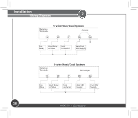
Installation Wiring Diagrams 2 Wallplate Terminals 4-wire Heat/Cool System Jumper Fan Relay Heat Relay Cool or Valve Contactor Heat/Cool 24V Supply Wallplate Terminals 5-wire Heat/Cool System No Jumper Fan Relay Heat Relay or Valve Cool contactor Heat 24V Supply Cool 24V Supply 20 44043-01 • 02/19/2010
-
 1
1 -
2
-
3
-
4
-
5
-
6
-
7
-
8
-
9
-
10
-
11
-
12
-
13
-
14
-
 15
15 -
 16
16 -
 17
17 -
 18
18 -
 19
19 -
 20
20 -
 21
21 -
 22
22 -
 23
23 -
 24
24 -
 25
25 -
26
-
27
-
28
-
29
-
30
-
31
-
32
-
33
-
34
-
35
 |
 |

44043-01
•
02/19/2010
20
2
Installation
Wiring Diagrams
Fan
Relay
Cool
Contactor
Jumper
Heat Relay
or Valve
Heat/Cool
24V Supply
Wallplate
Terminals
4-wire Heat/Cool System
Fan
Relay
Wallplate
Terminals
No Jumper
Cool
contactor
Heat Relay
or Valve
Heat 24V
Supply
Cool 24V
Supply
5-wire Heat/Cool System