Husqvarna 128C Owners Manual - Page 13
Assembly - 128l
 |
View all Husqvarna 128C manuals
Add to My Manuals
Save this manual to your list of manuals |
Page 13 highlights
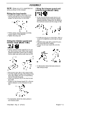
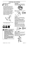
ASSEMBLY NOTE: Make sure unit is assembled cor- Fitting the trimmer guard and rectly as shown in this manual. trimmer head (Model 128C) Fitting the loop handle S Position the handle on the shaft. Note that the handle must be mounted be- tween the two arrows on the shaft. S Fit the correct trimmer guard (A) for use with the trimmer head. Hook the trimmer guard/combination guard onto the fitting on the shaft and secure with the wing nut (B). B A S Fit the screw, securing plate and wing nut as shown in the diagram. S Tighten the wing nut. Fitting the trimmer guard and trimmer head (Model 128L) C S Fit the dust cup (C) on the shaft. The nut must be completely covered by the dust cup. S Hold the dust cup with a wrench to prevent the shaft from rotating. S Screw the trimmer head (D) onto the shaft. S Fit the correct trimmer guard (A) for use with the trimmer head. Hook the trimmer guard/combination guard onto the fitting on the shaft and secure with the bolt (D). D D B C A A S Fit the drive disc (B) on the output shaft. S Turn the shaft until one of the holes in the drive disc aligns with the corresponding hole in the gear housing. S Insert hex wrench (C) in the hole to lock the shaft. S Screw on the trimmer head (H) in the opposite direction to the direction of rotation. H S To dismantle, follow the instructions in the reverse order. S To dismantle, follow the instructions in the reverse order. 115373927 Rev. 5 5/15/12 English--- 13
-
 1
1 -
2
-
3
-
4
-
5
-
6
-
7
-
 8
8 -
 9
9 -
 10
10 -
 11
11 -
 12
12 -
 13
13 -
 14
14 -
 15
15 -
 16
16 -
 17
17 -
 18
18 -
19
-
20
-
21
-
22
-
23
-
24
-
25
-
26
-
27
-
28
-
29
-
30
-
31
-
32
-
33
-
34
-
35
-
36
-
37
-
38
-
39
-
40
-
41
-
42
-
43
-
44
-
45
-
46
-
47
-
48
-
49
-
50
-
51
-
52
-
53
-
54
-
55
-
56
-
57
-
58
-
59
-
60
-
61
-
62
-
63
-
64
-
65
-
66
-
67
-
68
-
69
-
70
-
71
 |
 |
