IBM 1735R16 User Guide
IBM 1735R16 Manual
 |
View all IBM 1735R16 manuals
Add to My Manuals
Save this manual to your list of manuals |
IBM 1735R16 manual content summary:
- IBM 1735R16 | User Guide - Page 1
RCM NetBAY Advanced Connectivity Technology Remote Console Manager Installer and User Guide For 32P1651, 1735-R16 and 32P1653 - IBM 1735R16 | User Guide - Page 2
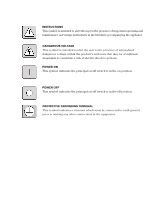
user to the presence of important operating and maintenance (servicing) instructions in the literature accompanying the appliance. DANGEROUS VOLTAGE This indicates the principal on/off switch is in the on position. POWER OFF This symbol indicates the principal on/off switch is in the off position. - IBM 1735R16 | User Guide - Page 3
- IBM 1735R16 | User Guide - Page 4
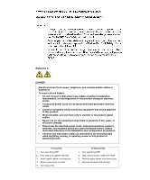
damage. • Disconnect the attached power cords, telecommunications systems, networks, and modems before you open the device covers, unless instructed otherwise in the installation and configuration procedures. • Connect and disconnect cables as described in the following table when installing, moving - IBM 1735R16 | User Guide - Page 5
RCM Installer and User Guide - IBM 1735R16 | User Guide - Page 6
- IBM 1735R16 | User Guide - Page 7
5 Chapter 2: Installation Getting Started 9 Installing Your RCM 10 Cabling the RCM 13 Chapter 3: Analog Port Operation Controlling Your System at 49 Appendices Appendix A: FLASH Upgrades 53 Appendix B: Technical Specifications 57 Appendix C: Hardware Maintenance Information . . . 58 - IBM 1735R16 | User Guide - Page 8
1 Product Overview Contents Features and Benefits 3 Safety Precautions 5 - IBM 1735R16 | User Guide - Page 9
- IBM 1735R16 | User Guide - Page 10
time. The RCM consists of a rack mountable keyboard, video and mouse (KVM) switch configurable for analog or digital connectivity. Each RCM has 16 on the attached computers. Digital users access the RCM and all attached systems via Ethernet from a PC running the IBM NetBAY Virtual Console software - IBM 1735R16 | User Guide - Page 11
system server. Multiple servers can be accessed by one user; each additional computer's video will appear in a separate program window. KCO Cables KCO Cables Switch Rack of Servers Rack of Servers CCO Cable RCM Chained C2T Servers TCP/IP Analog Connection TCP/IP Remote Workstations Figure - IBM 1735R16 | User Guide - Page 12
covers, unless instructed otherwise in problems when using IBM products: • If the building has 3-phase AC power, ensure that the computer and monitor are on the same phase. For best results, they should be on the same circuit. • Use only IBM-supplied cable to connect computers and KVM switches. IBM - IBM 1735R16 | User Guide - Page 13
and User Guide • Test AC outlets at the computer and monitor for proper polarity and grounding. • Use only with grounded outlets at both the computer and monitor. When using a backup uninterruptible power supply, power the computer, the monitor and the RCM off the supply. NOTE: The AC inlet - IBM 1735R16 | User Guide - Page 14
2 Installation Contents Getting Started 9 Installing Your RCM 10 Cabling the RCM 13 - IBM 1735R16 | User Guide - Page 15
- IBM 1735R16 | User Guide - Page 16
per attached PS/2 server or switch • One UCO cable per attached USB server • One CCO cable per attached IBM C2T server chain Setting up your network The RCM system uses IP addresses to uniquely identify the RCMs and the computers running NetBAY VC software. The RCM supports both BootP (a subset of - IBM 1735R16 | User Guide - Page 17
Installer and User Guide Installing Your RCM Your RCM ships with rack mounting brackets. Before installing the RCM and other components in the rack networks, and modems before you open the device covers, unless instructed otherwise in the installation and configuration procedures. • Connect and - IBM 1735R16 | User Guide - Page 18
are not already spaced for this installation. Figure 2.1: RCM Vertical Installation Horizontal installation in the 1U rack mounting 's side brackets with the screw holes in the switch. 2. With a Phillips screwdriver, fasten the mounting brackets to the switch using two 8/32" x 1/2" pan head screws - IBM 1735R16 | User Guide - Page 19
12 RCM Installer and User Guide 4. Mount the switch assembly to the rack cabinet by matching the holes in the "short side" of each bracket to an appropriate set of slots in the bracket and the holes in the mounting rail, then into the cage nuts or clip nuts. Figure 2.2: RCM Horizontal Installation - IBM 1735R16 | User Guide - Page 20
CAT 5 Up to 16 chained servers per ARI port CAT 5 CAT 5 ARI Ports IBM NetBAY Switch KCO Server Server Server KVM Up to 16 CAT 5 UCO chained servers per ARI port Server Server Server Figure 2.3: Basic RCM Configuration ATTENTION: To reduce the risk of electric shock or damage to your - IBM 1735R16 | User Guide - Page 21
14 RCM Installer and User Guide Statement 4: DANGER Electrical current from power, telephone, and communication cables is systems, networks, and modems before you open the device covers, unless instructed otherwise in the installation and configuration procedures. • Connect and disconnect cables - IBM 1735R16 | User Guide - Page 22
15 To configure the RCM hardware: 1. You will see the Terminal Applications menu with six options. Select option 1, Network Configuration. Figure 2.4: Network Configuration Menu 2. Select option 1 to set your network speed. When possible, you should set your connection manually without relying on the - IBM 1735R16 | User Guide - Page 23
Installer and User Guide 3. Set the pointer speed to Slow. Do this for any Windows NT user account that will be accessing the Windows NT system through the RCM. For Microsoft Windows 2000/Windows XP: 1. From the desktop, select Start - Settings - Control Panel - Mouse. 2. Click on the Motion tab - IBM 1735R16 | User Guide - Page 24
last KCO cable in the chain. To chain servers together using UCO cables: CAT 5 cable up to 10 meters (32.8 feet) UCO Cable RCM or LCM (RCM shown) UCO Cable Server 1 UCO Cable Server 2 Terminator Figure 2.6: Chaining Servers Together with UCO Cables Server 3 1. Locate the UCO cables and CAT - IBM 1735R16 | User Guide - Page 25
to 24 servers, depending on how many servers you can attach to your legacy KVM switch. RCM KCO Cable Terminator IBM NetBAY Console Switch Server 1 Figure 2.7: RCM Configuration with a Legacy KVM Switch 1. Mount the KVM switch into your rack cabinet. Locate a length of CAT 5 cabling to connect your - IBM 1735R16 | User Guide - Page 26
manufacturer's recommendations. 6. Repeat steps 2-5 for all cascade switches to be attached to your system. To operate your RCM with a cascaded multi-user legacy switch: You can cascade a NetBAY 2x8 Console Switch under your RCM or LCM. In a cascaded configuration, the remote and analog workstations - IBM 1735R16 | User Guide - Page 27
20 RCM Installer and User Guide Analog Workstation Remote Workstation KCO Cable A KCO Cable B Second KCO connects to user port on the front of the switch IBM NetBAY 2x8 Switch Server 1 Server 2 Server 3 KVM Figure 2.8: Cascaded Multi-user Legacy Switch Configuration To connect the network and - IBM 1735R16 | User Guide - Page 28
the user guide that comes with your system. 2. The languages should now be synchronized. Setting up your RCM/NetBAY VC system The RCM system has your system. Proceed to Chapter 3 in this Installer and User Guide for detailed instructions on OSCAR setup and configuration. Once your servers are named, - IBM 1735R16 | User Guide - Page 29
22 RCM Installer and User Guide - IBM 1735R16 | User Guide - Page 30
3 Analog Port Operation Contents Controlling Your System at the Analog Port 25 Viewing and Selecting Ports and Servers 25 Configuring OSCAR 28 Viewing and Disconnecting Users 37 Running System Diagnostics 38 Resetting Your PS/2 Keyboard and Mouse 40 Displaying Version Information 40 Scanning - IBM 1735R16 | User Guide - Page 31
- IBM 1735R16 | User Guide - Page 32
RCM uses the On-Screen Configuration and Activity Reporting interface (OSCAR®) for IBM, which utilizes intuitive menus to configure your system and select computers which a server is connected. If you connect a legacy KVM switch to the RCM, the port numbering displays the ARI port first, then Guide. - IBM 1735R16 | User Guide - Page 33
26 RCM Installer and User Guide Viewing the status of your RCM system The status of the servers in your is online. KCO, UCO or CCO is offline or is not operating properly. Connected switch is online. Connected switch is offline or is not operating properly. KCO, UCO or CCO cable is being upgraded - IBM 1735R16 | User Guide - Page 34
designated letters. Closes the current dialog box and returns to the previous one. Selects the OK button, then returns to the previous dialog box. Completes a switch in the Main dialog box and exits OSCAR. In a text box, it selects the text for editing and enables the Left and Right Arrow keys - IBM 1735R16 | User Guide - Page 35
28 RCM Installer and User Guide OSCAR Navigation Basics (continued) This Keystroke Does This Print Screen, Backspace Toggles back to previous selection if no other keystrokes have been typed. Print Screen, - IBM 1735R16 | User Guide - Page 36
Identify the appropriate number of ports on an attached cascade switch. Names Identify servers by unique names. Assigning server names Use /server to another ARI port, the name and configuration will be recognized by the RCM. NOTE: If a server is turned off, its respective CO cable will not - IBM 1735R16 | User Guide - Page 37
30 RCM Installer and User Guide Figure 3.3: Names Dialog Box NOTE: If the server list changes, the mouse cursor will turn into an hourglass as the list is automatically updated. No - IBM 1735R16 | User Guide - Page 38
unit, you will need to specify the number of ports on the cascade switch through the Devices dialog box. The RCM recognizes KVM switches. You will see an Sw-8 appear in the Type category. When you select that switch from the list, the Modify button appears, allowing you to assign the appropriate - IBM 1735R16 | User Guide - Page 39
32 RCM Installer and User Guide Figure 3.6: Device Modify Dialog Box 3. Choose the number of ports supported by your switch and click OK. 4. Repeat steps 1-3 for each port that needs a device type assigned. 5. Click OK in the Devices dialog box to save settings. NOTE: Changes - IBM 1735R16 | User Guide - Page 40
Ø will instantly launch OSCAR with no delay. 2. Click OK. Setting a Screen Delay Time allows you to complete a soft switch without OSCAR displaying. To perform a soft switch, see Soft switching in this chapter. Controlling the status flag The status flag displays on your desktop and shows the name - IBM 1735R16 | User Guide - Page 41
34 RCM Installer and User Guide Figure 3.8: Flag Dialog Box To determine how the status flag is displayed: 1. Select Name or eID to determine what information will be displayed. 2. Select Displayed to show the flag all the time or select Timed to display the flag for only five seconds after switching. - IBM 1735R16 | User Guide - Page 42
Chapter 3: Analog Port Operation 35 Use the Security dialog box to lock your console with password protection, set or change your password and enable the screen saver. NOTE: If a password has been previously set, you will have to enter the password before you can access the Security dialog box. To - IBM 1735R16 | User Guide - Page 43
36 RCM Installer and User Guide ATTENTION: Monitor damage can result from the use of Energy mode with monitors not compliant with ENERGY STAR. 5. (Optional) Click Test to activate the screen - IBM 1735R16 | User Guide - Page 44
) by a digital user via the Virtual Console software. See the Preempting the local user in the Virtual Console Software Installer and User Guide for additional information. To view current user connections: 1. Press Print Screen. The Main dialog box will appear. 2. Click Commands - User Status. The - IBM 1735R16 | User Guide - Page 45
38 RCM Installer and User Guide 4. Click OK to disconnect the user and return to the User that inter-board communication sub-systems are accessible and functional Switch Controller The Switch Controller test verifies the switch matrix controller is accessible and functional Local and Remote Video - IBM 1735R16 | User Guide - Page 46
: Suspect COs Dialog Box a. Make a note of each CO in the list. In Figure 3.14, the first CO (Sw-4) is attached to channel 4 of a cascade switch, the second (???) is noncommunicative and the third (Srvr) is attached directly to a server. You may want to troubleshoot each of these COs. - IBM 1735R16 | User Guide - Page 47
40 RCM Installer and User Guide Resetting Your PS/2 Keyboard and Mouse If your PS/2 RCM. With communication re-established between the server and the RCM, functionality is restored to the user. NOTE: This function is for Microsoft Windows-based computers only. Resetting the PS/2 on a computer - IBM 1735R16 | User Guide - Page 48
Chapter 3: Analog Port Operation 41 3. Click Digital to view the Digitizer unit firmware versions. The Digital Version dialog box appears. The top section identifies the Digitizer subsystem versions. The center section identifies the current network settings. Click X or press Escape to return to the - IBM 1735R16 | User Guide - Page 49
42 RCM Installer and User Guide Figure 3.18: CO Version Dialog Box 6. Click X to close the Version dialog box. Scanning Your System In scan mode, the RCM automatically scans from port to port (server to server). You can select up to 16 servers from a list of all servers attached to your unit. - IBM 1735R16 | User Guide - Page 50
Chapter 3: Analog Port Operation 43 Click the checkbox next to the servers you wish to scan. -orDouble-click on a server's name or port. -orPress Alt and the number of the server you wish to scan. You can select up to 16 servers. 4. In the Scan Time box, type the number of seconds (from 3 to 99) of - IBM 1735R16 | User Guide - Page 51
44 RCM Installer and User Guide To cancel scan mode: 1. Select a server if OSCAR is open. -orMove the the Caps Lock and Num Lock modes must be the same on all keyboards. While the RCM attempts to send keystrokes to the selected servers simultaneously, some servers may inhibit and thereby delay - IBM 1735R16 | User Guide - Page 52
Chapter 3: Analog Port Operation 45 To broadcast to selected servers: 1. From the Broadcast dialog box, select the mouse and keyboard checkboxes for the servers that are to receive the broadcast commands. -orPress the Up or Down Arrow keys to move the cursor to the target server. Then press Alt+K to - IBM 1735R16 | User Guide - Page 53
46 RCM Installer and User Guide - IBM 1735R16 | User Guide - Page 54
4 Terminal Operations Contents Configuring the Terminal Menu 49 - IBM 1735R16 | User Guide - Page 55
- IBM 1735R16 | User Guide - Page 56
Terminal menu: 1. Connect a terminal or PC running terminal emulation software (such as HyperTerminal) to the configuration port on the back panel of the RCM using a straight-through serial cable. The terminal should be set to 9600 baud, 8 bits, 1 stop bit, no parity and no flow control. The terminal - IBM 1735R16 | User Guide - Page 57
Installer and User Guide Firmware Management This menu option contains the FLASH Download command. The FLASH Download selection allows you to keep your RCM firmware current with upgrades available from IBM. For more information see Appendix A: FLASH Upgrades. Enable Debug Messages This menu option - IBM 1735R16 | User Guide - Page 58
Appendices Contents Appendix A: FLASH Upgrades 53 Appendix B: Technical Specifications 57 Appendix C: Hardware Maintenance Information . . . 58 Appendix D: Notices 59 Appendix E: Electronic Emission Notices 61 - IBM 1735R16 | User Guide - Page 59
- IBM 1735R16 | User Guide - Page 60
you will need to download the latest FLASH firmware from IBM at http://www.ibm.com/pc/support or copy the FLASH upgrade file (.fl file extension) 's IP address from step 4 above. The last number must be different. If the RCM's IP address is not correct, change it as follows: Type 3 to select IP - IBM 1735R16 | User Guide - Page 61
54 RCM Installer and User Guide 7. From the main menu, type 2 to select Firmware Management. The current and press Enter. 10. Confirm the TFTP download by typing y or yes and pressing Enter. 11. The RCM will verify the file you downloaded is valid. Next you will be prompted to confirm the upgrade. Type - IBM 1735R16 | User Guide - Page 62
Appendices 55 Figure A.2: CO Upgrade Dialog Box 4. The CO Upgrade dialog box appears. Click OK to initiate the upgrade and return to the CO Status dialog box. To upgrade CO firmware individually: 1. Press Print Screen. The Main dialog box will appear. 2. Click Commands - Display Versions. The Version - IBM 1735R16 | User Guide - Page 63
56 RCM Installer and User Guide Figure A.4: CO Selection Dialog Box 4. Select a KCO, UCO or CCO cable to upgrade and click the Version button. The CO Version dialog box appears. Figure A.5: - IBM 1735R16 | User Guide - Page 64
Appendices 57 Appendix B: Technical Specifications RCM Product Specifications Server Ports Number 16 Types KCO, CCO, UCO intelligent cables Connectors RJ45 Sync Types Separate horizontal and vertical Plug and Play DDC2B - IBM 1735R16 | User Guide - Page 65
Installer and User Guide Appendix C: Hardware Maintenance Information This appendix contains information about IBM Field Replaceable Unit (FRU) availability for the RCM. Troubleshooting and servicing of complex problems should be performed only by trained service personnel. Field Replaceable Unit - IBM 1735R16 | User Guide - Page 66
right may be used instead. However, it is the user's responsibility to evaluate and verify the operation of any non-IBM product, program, or service. IBM may have patents or pending patent applications covering subject matter described in this document. The furnishing of this document does not - IBM 1735R16 | User Guide - Page 67
60 RCM Installer and User Guide Trademarks IBM and NetBAY are trademarks of supported drives available from IBM. Maximum memory may require replacement of the standard memory with an optional memory module. IBM makes no representation or warranties regarding non-IBM products and services - IBM 1735R16 | User Guide - Page 68
and, if not installed and used in accordance with the instruction manual, may cause harmful interference to radio communications. Operation of this and connectors must be used in order to meet FCC emission limits. IBM is not responsible for any radio or television interference caused by using other - IBM 1735R16 | User Guide - Page 69
RCM Installer and User Guide European Union EMC Directive conformance statement This product is in conformity with the protection requirements of EU Council Directive 89/336/EEC on the approximation of the laws of the Member States relating to electromagnetic compatibility. IBM non-IBM option cards - IBM 1735R16 | User Guide - Page 70
- IBM 1735R16 | User Guide - Page 71
59P2181 Rev.C 590245001B
-
 1
1 -
 2
2 -
 3
3 -
 4
4 -
 5
5 -
 6
6 -
 7
7 -
8
-
9
-
10
-
11
-
12
-
13
-
14
-
15
-
16
-
17
-
18
-
19
-
20
-
21
-
22
-
23
-
24
-
25
-
26
-
27
-
28
-
29
-
30
-
31
-
32
-
33
-
34
-
35
-
36
-
37
-
38
-
39
-
40
-
41
-
42
-
43
-
44
-
45
-
46
-
47
-
48
-
49
-
50
-
51
-
52
-
53
-
54
-
55
-
56
-
57
-
58
-
59
-
60
-
61
-
62
-
63
-
64
-
65
-
66
-
67
-
68
-
69
-
70
-
71
 |
 |

RCM
NetBAY Advanced Connectivity Technology
Remote Console Manager
Installer and User Guide
For 32P1651, 1735-R16 and 32P1653