IBM 2498B24 User Guide - Page 26
Supported connectivity, Port side of the switch, Item number, Description - interoperability
 |
UPC - 883436031462
View all IBM 2498B24 manuals
Add to My Manuals
Save this manual to your list of manuals |
Page 26 highlights
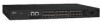
logical ISL switch with a speed of up to 64 Gbits/sec (128 Gbits/sec full duplex) for optimal bandwidth utilization and load balancing. v Advanced Zoning. v Intelligent management and monitoring with Web Tools, Fabric Watch, and Performance Monitor. v Adaptive Networking Services uses network intelligence to anticipate congestion and to dynamically make adjustments in the fabric so that application traffic continues to flow v Dynamic Path Selection (DPS) optimizes fabric-wide performance and load balancing by automatically routing data to the most efficient available path in the fabric. v Light emitting diodes (LEDs) to indicate system power, system status, Ethernet speed and link status, and port status. Supported connectivity Specific details on supported operating systems, servers, and devices, storage products attachability, SAN connectivity products, and configuration options can be found in the interoperability matrices at the following web site: www.ibm.com/servers/storage/support/san. Port side of the switch Figure 1 shows the port side of the switch. All LEDs are on the port side of the switch: the nonport side is used to allow the free flow of air. The switch enclosure has forced-air cooling, with the fans pushing the air from the nonport side of the chassis through the enclosure, exhausting to the port side. For a complete description of the locations and interpretations of these LEDs, see "Interpreting LED activity" on page 21. 1 2 34 5 6 7 B24_0001 1 Figure 1. Port side of the switch Item number 1 2 3 4 5 6 7 2 SAN24B-4 Express Installation, Service, and User Guide Description System status (top) and power (bottom) LEDs System RS232 console port (RJ-45) Ethernet Port with two Ethernet status LEDs USB port Fibre Channel status LEDs Fibre Channel Ports (24) AC power receptacle
-
 1
1 -
2
-
3
-
4
-
5
-
6
-
7
-
8
-
9
-
10
-
11
-
12
-
13
-
14
-
15
-
16
-
17
-
18
-
19
-
20
-
 21
21 -
 22
22 -
 23
23 -
 24
24 -
 25
25 -
 26
26 -
 27
27 -
 28
28 -
 29
29 -
 30
30 -
 31
31 -
32
-
33
-
34
-
35
-
36
-
37
-
38
-
39
-
40
-
41
-
42
-
43
-
44
-
45
-
46
-
47
-
48
-
49
-
50
-
51
-
52
-
53
-
54
-
55
-
56
-
57
-
58
-
59
-
60
-
61
-
62
-
63
-
64
-
65
-
66
-
67
-
68
-
69
-
70
-
71
-
72
-
73
-
74
-
75
-
76
-
77
 |
 |
