IBM 4368E3U User Manual - Page 41
Installing, memory, module
 |
View all IBM 4368E3U manuals
Add to My Manuals
Save this manual to your list of manuals |
Page 41 highlights
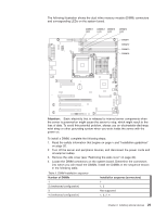
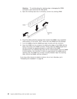
Installing a memory module The following notes describe the types of dual inline memory modules (DIMMs) that the server supports and other information that you must consider when you install DIMMs: v The server supports only industry-standard, 1.8 V, 240-pin double-data-rate 2 (DDR2), 667 or 800 MHz, PC2-5300 or PC2-6400, unbuffered, synchronous dynamic random-access memory (SDRAM) dual inline memory modules (DIMMs) with error correcting code (ECC). These DIMMs must be compatible with the latest DDR2 667 or 800 MHz SDRAM unbuffered DIMM specification. For a list of supported optional devices for the server, see http://www.ibm.com/servers/ eserver/serverproven/compat/us/. v The optional DIMMs that are available for the server are 512 MB, 1 GB, and 2 GB. The server supports a minimum of 512 MB and a maximum of 8 GB of system memory. v Some servers come with one 512 MB DIMM, two 512 MB DIMMs, or two 1 GB DIMMs installed. Depending on the DIMM sizes that are installed in your server, the server can support one, two, or four DIMMs. The 512 MB DIMM option kit contains one DIMM; however, the 1 GB DIMM and 2 GB option kits each contain two DIMMs. v The system board contains four DIMM connectors and supports two-way memory interleaving. For two-way memory interleaving, DIMMs must be installed in matched pairs. If one DIMM is installed in the DIMM 1 connector, when you install an additional DIMM, it must be installed in the DIMM 3 connector, and it must be the same size, speed, type, and technology as the DIMM in the DIMM 1 connector. You can use compatible DIMMs from various manufacturers. If you install a second pair of DIMMs in the DIMM 2 and DIMM 4 connectors, they do not have to be the same size, speed, type, and technology as the DIMMs in the DIMM 1 and DIMM 3 connectors. However, the size, speed, type, and technology of the DIMMs that you install in the DIMM 2 and DIMM 4 connectors must match each other. v The maximum operating speed of the server is determined by the slowest DIMM in the server. v The server can operate in single-channel mode or dual-channel mode. v DIMM population is based on single-rank, double-rank, or combined single-rank and double-rank DIMMs. DIMMs must be installed in order, starting with the DIMM connector that is farthest from the memory controller hub. Double-rank DIMMs must be installed in the DIMM connector that is farthest from the memory controller hub when you install a combination of single-rank and double-rank DIMMs. The following tables show examples of populating the server with different combinations of single-rank and double-rank DIMMs and different operating modes. Table 2. Single-channel mode with single-rank and double-rank DIMMs Channel 0 Channel 1 DIMM 1 DIMM 2 DIMM 3 DIMM 4 Single-rank Double-rank Single-rank Single-rank Chapter 2. Installing optional devices 27
-
 1
1 -
2
-
3
-
4
-
5
-
6
-
7
-
8
-
9
-
10
-
11
-
12
-
13
-
14
-
15
-
16
-
17
-
18
-
19
-
20
-
21
-
22
-
23
-
24
-
25
-
26
-
27
-
28
-
29
-
30
-
31
-
32
-
33
-
34
-
35
-
 36
36 -
 37
37 -
 38
38 -
 39
39 -
 40
40 -
 41
41 -
 42
42 -
 43
43 -
 44
44 -
 45
45 -
 46
46 -
47
-
48
-
49
-
50
-
51
-
52
-
53
-
54
-
55
-
56
-
57
-
58
-
59
-
60
-
61
-
62
-
63
-
64
-
65
-
66
-
67
-
68
-
69
-
70
-
71
-
72
-
73
-
74
-
75
-
76
-
77
-
78
-
79
-
80
-
81
-
82
-
83
-
84
-
85
-
86
-
87
-
88
-
89
-
90
-
91
-
92
-
93
-
94
-
95
-
96
-
97
-
98
-
99
-
100
-
101
-
102
 |
 |