IBM 4368E3U User Manual - Page 55
Installing, adapter
 |
View all IBM 4368E3U manuals
Add to My Manuals
Save this manual to your list of manuals |
Page 55 highlights
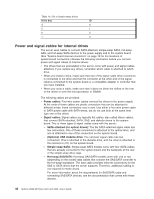
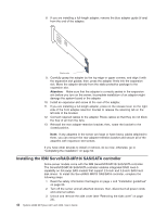
For a list of supported optional devices for the server, see http://www.ibm.com/servers/eserver/serverproven/compat/us/. Installing an adapter The following notes describe the types of adapters that the server supports and other information that you must consider when you install an adapter. v Locate the documentation that comes with the adapter and follow those instructions in addition to the instructions in this section. If you have to change the switch setting or jumper settings on the adapter, follow the instructions that come with the adapter. v Read the documentation that comes with your operating system. v The server comes with the following adapter connectors or slots: - Slot 1, PCI Express x8 - Slot 2, PCI Express x4 (x1) Important: The x1 designation in parentheses for slot 2 identifies an x4 slot that is designed to support x1 and x4 adapters that can downshift to operate at the x1 bandwidth. For example, if you install an x4 adapter in slot 2 that can downshift to x1 bandwidth, it will run at the x1 bandwidth. The x4 connector (slot 2) can be used for x1 and x4 adapters. Check the information that comes with your adapter for compatibility information. - Slot 3, PCI-X 64-bit/133 MHz Note: PCI-X slot 3 is enabled when the optional mini-PCI-X enablement card is installed in the mini-PCI slot on the system board. When no mini-PCI-X enablement card is installed, PCI-X slot 3 has no function. - Slot 4, PCI 32-bit/33 MHz - Slot 5, PCI 32-bit/33 MHz v Some server models come with a mini-SAS/SATA RAID controller installed. The mini-SAS/SATA RAID controller enables integrated RAID levels-0 and level-1. Some models also come with a ServeRAID-MR10i SAS/SATA controller that enables integrated RAID level 5 capability. v The ServeRAID-MR10i SAS/SATA controller must be installed in slot 1, PCI Express x8. v You can install the mini-PCI-X enablement card or the mini-SAS/SATA RAID controller in the mini-PCI slot on the system board. v When an optional mini-PCI-X enablement card is installed in the mini-PCI slot, it passes PCI-X signals from the mini-PCI-X enablement card to PCI-X slot 3. v When an optional mini-PCI-X enablement card is installed in the server, the server cannot support RAID levels-0 and level-1. v You can install full-length adapters that are included in the ServerProven® list in slots 1 through 5 (depending on your model). v The 64-bit slot 3 supports 3.3 V PCI-X adapters. v The 32-bit slots 4 and 5 support 5.0 V keyed PCI adapters; they do not support 3.3 V keyed adapters. Universal adapters are supported in slots 4 and 5 if they are universally keyed. v An optional IBM Remote Supervisor Adapter II SlimLine can be installed only in its dedicated connector on the system board. See "System-board internal connectors" on page 16 for the location of the connector. For additional information, see the documentation that comes with this adapter. Chapter 2. Installing optional devices 41
-
 1
1 -
2
-
3
-
4
-
5
-
6
-
7
-
8
-
9
-
10
-
11
-
12
-
13
-
14
-
15
-
16
-
17
-
18
-
19
-
20
-
21
-
22
-
23
-
24
-
25
-
26
-
27
-
28
-
29
-
30
-
31
-
32
-
33
-
34
-
35
-
36
-
37
-
38
-
39
-
40
-
41
-
42
-
43
-
44
-
45
-
46
-
47
-
48
-
49
-
 50
50 -
 51
51 -
 52
52 -
 53
53 -
 54
54 -
 55
55 -
 56
56 -
 57
57 -
 58
58 -
 59
59 -
 60
60 -
61
-
62
-
63
-
64
-
65
-
66
-
67
-
68
-
69
-
70
-
71
-
72
-
73
-
74
-
75
-
76
-
77
-
78
-
79
-
80
-
81
-
82
-
83
-
84
-
85
-
86
-
87
-
88
-
89
-
90
-
91
-
92
-
93
-
94
-
95
-
96
-
97
-
98
-
99
-
100
-
101
-
102
 |
 |