IBM 4368E3U User Manual - Page 45
Installing, drive
 |
View all IBM 4368E3U manuals
Add to My Manuals
Save this manual to your list of manuals |
Page 45 highlights
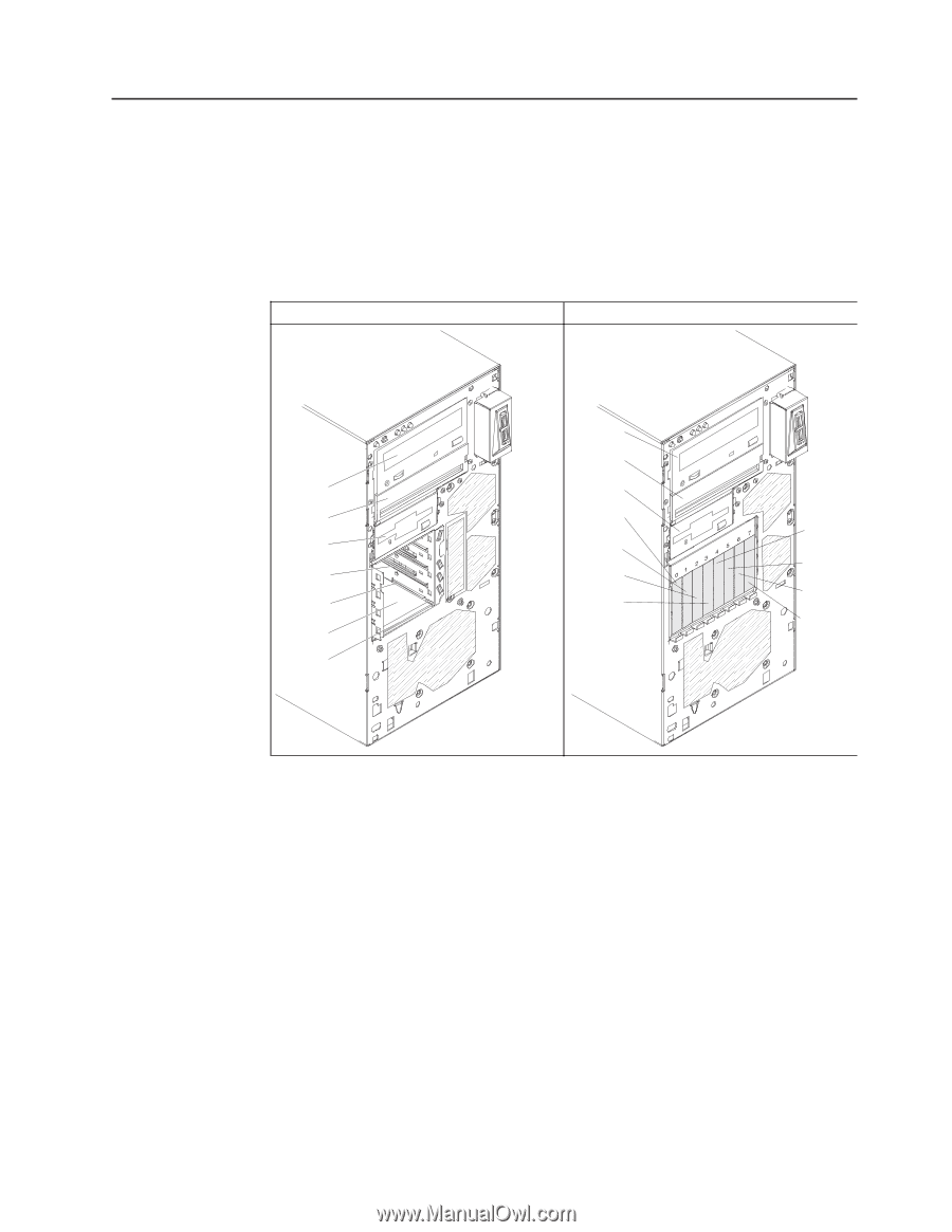
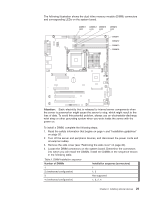
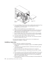
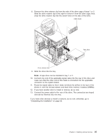
Installing a drive Depending on the server model, a DVD-ROM or multiburner drive might be installed in the server. The server supports 2.5-inch or 3.5-inch hot-swap SAS, 3.5-inch hot-swap SATA, or 3.5-inch simple-swap SATA hard disk drives (depending on the model). The following illustrations show the locations of the drive bays. Some models have seven drive bays, and some models have eleven drive bays. Table 6. Drive bays on the server models Seven drive-bay model Eleven drive-bay model Bay 1 Bay 2 Bay 3 Bay 4 Bay 5 Bay 6 Bay 7 Bay 1 Bay 2 Bay 3 Bay 4 Bay 5 Bay 6 Bay 7 Bay 8 Bay 9 Bay 10 Bay 11 The following notes describe the types of drives that the server supports and other information that you must consider when you install a drive: v Make sure that you have all the cables and other equipment that are specified in the documentation that comes with the drive. v Select the bay in which you want to install the drive. v Check the instructions that come with the drive to determine whether you have to set any switches or jumpers on the drive. If you are installing a SAS or SATA device, be sure to set the SAS or SATA ID for that device. v Optional internal or external USB diskette drives, tape drives, DVD-ROM, and multiburner drives are examples of removable-media drives. You can install removable-media drives in bays 1, 2, and 3 only. v The SATA removable-media drives that you install in bay 1 connects to the SATA 4 connector on the system board and the drive in bay 2 connects to the SATA 5 connector on the system board. v To install a 3.5- inch drive in a 5.25-inch bay, you must use the 5.25-inch conversion kit. Chapter 2. Installing optional devices 31
-
 1
1 -
2
-
3
-
4
-
5
-
6
-
7
-
8
-
9
-
10
-
11
-
12
-
13
-
14
-
15
-
16
-
17
-
18
-
19
-
20
-
21
-
22
-
23
-
24
-
25
-
26
-
27
-
28
-
29
-
30
-
31
-
32
-
33
-
34
-
35
-
36
-
37
-
38
-
39
-
 40
40 -
 41
41 -
 42
42 -
 43
43 -
 44
44 -
 45
45 -
 46
46 -
 47
47 -
 48
48 -
 49
49 -
 50
50 -
51
-
52
-
53
-
54
-
55
-
56
-
57
-
58
-
59
-
60
-
61
-
62
-
63
-
64
-
65
-
66
-
67
-
68
-
69
-
70
-
71
-
72
-
73
-
74
-
75
-
76
-
77
-
78
-
79
-
80
-
81
-
82
-
83
-
84
-
85
-
86
-
87
-
88
-
89
-
90
-
91
-
92
-
93
-
94
-
95
-
96
-
97
-
98
-
99
-
100
-
101
-
102
 |
 |