IBM 8482 User Manual - Page 49
SCSI IDs for hot-swap hard disk drives, Installing a non-hot-swap SCSI hard disk drive in bay 4
 |
UPC - 000435244659
View all IBM 8482 manuals
Add to My Manuals
Save this manual to your list of manuals |
Page 49 highlights
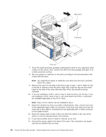
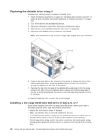
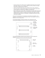
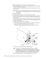
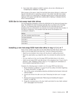
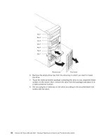
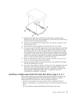
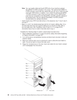
9. If you have other options to install or remove, do so now; otherwise go to "Completing the installation" on page 50. After turning on the server, check the hard disk drive status indicator to make sure that the hard disk drive is operating correctly. If the amber hard disk drive status LED for a drive is lit continuously, it indicates that the drive is faulty and must be replaced. If the green hard disk drive activity LED is flashing, it indicates that the drive is being accessed. SCSI IDs for hot-swap hard disk drives The hot-swap-drive backplane controls the SCSI IDs for the internal hot-swap drive bays. The SCSI ID for each hot-swap hard disk drive is printed on the hot-swap lock bar. The following table lists the SCSI IDs for the hard disk drives and backplane that are connected to one channel in hot-swap hard disk drive models. In the typical configuration, the standard hard disk drives and backplane are connected to channel A. Device AIC 7901 controller (mini-PCI-X slot) Hot-swap backplane Drive bay 7 Drive bay 6 Drive bay 5 SCSI ID 7 9 12 13 14 Installing a non-hot-swap SCSI hard disk drive in bay 4, 5, 6, or 7 Some server models come with non-hot-swap SCSI hard disk drives. Before you install a non-hot-swap SCSI hard disk drive, read the following information: v Read the documentation that comes with the drive for cabling instructions. v Route the cable before you install the drive. Do not block the airflow from the fans. v You can install up to four non-hot-swap SCSI hard disk drives in the server. v Install non-hot-swap SCSI hard disk drives in this sequence: bay 7, bay 6, bay 5, and bay 4. See "Installing a drive in bay 2 or 4" on page 32 for information on how to install a hard disk drive in bay 4. Complete the following steps to install a non-hot-swap SCSI hard disk drive: 1. Read "Installation guidelines" on page 23 and the safety information beginning at "Safety information" on page 107. 2. Turn off the server and peripheral devices and disconnect all power cords and external cables. 3. Unlock and remove the side cover (see "Removing the side cover" on page 26). 4. Remove the support bracket (see "Removing and installing the support bracket" on page 28). 5. Grasp the recessed area on the door hatch and rotate the door hatch outward until it disengages from the server. Chapter 4. Installing options 39
-
 1
1 -
2
-
3
-
4
-
5
-
6
-
7
-
8
-
9
-
10
-
11
-
12
-
13
-
14
-
15
-
16
-
17
-
18
-
19
-
20
-
21
-
22
-
23
-
24
-
25
-
26
-
27
-
28
-
29
-
30
-
31
-
32
-
33
-
34
-
35
-
36
-
37
-
38
-
39
-
40
-
41
-
42
-
43
-
 44
44 -
 45
45 -
 46
46 -
 47
47 -
 48
48 -
 49
49 -
 50
50 -
 51
51 -
 52
52 -
 53
53 -
 54
54 -
55
-
56
-
57
-
58
-
59
-
60
-
61
-
62
-
63
-
64
-
65
-
66
-
67
-
68
-
69
-
70
-
71
-
72
-
73
-
74
-
75
-
76
-
77
-
78
-
79
-
80
-
81
-
82
-
83
-
84
-
85
-
86
-
87
-
88
-
89
-
90
-
91
-
92
-
93
-
94
-
95
-
96
-
97
-
98
-
99
-
100
-
101
-
102
-
103
-
104
-
105
-
106
-
107
-
108
-
109
-
110
-
111
-
112
-
113
-
114
-
115
-
116
-
117
-
118
-
119
-
120
-
121
-
122
-
123
-
124
-
125
-
126
-
127
-
128
-
129
-
130
-
131
-
132
-
133
-
134
-
135
-
136
-
137
-
138
-
139
-
140
-
141
-
142
-
143
-
144
-
145
-
146
-
147
-
148
-
149
-
150
-
151
-
152
-
153
-
154
-
155
-
156
-
157
-
158
-
159
-
160
 |
 |