IBM 8482 User Manual - Page 52
at Safety information
 |
UPC - 000435244659
View all IBM 8482 manuals
Add to My Manuals
Save this manual to your list of manuals |
Page 52 highlights
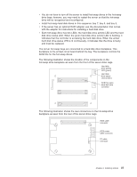
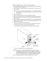
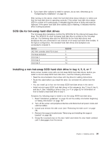
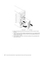
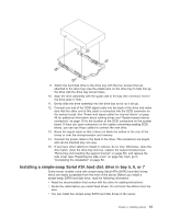
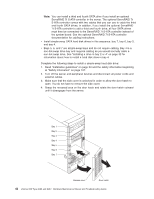
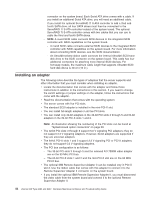
Note: You can install a third and fourth SATA drive if you install an optional ServeRAID 7t S-ATA controller in the server. The optional ServeRAID 7t S-ATA controller comes with two cables that you can use to cable the third and fourth SATA drives. In addition, if you install the optional ServeRAID 7t S-ATA controller to add a third and fourth drive, all four SATA drives must then be connected to the ServeRAID 7t S-ATA controller instead of the system board. See the optional ServeRAID 7t S-ATA controller documentation for cabling instructions. v Install simple-swap SATA hard disk drives in this sequence: bay 7, bay 6, bay 5, and bay 4. v Bays 5, 6, and 7 are simple-swap bays and do not require cabling. Bay 4 is a non-hot-swap drive bay and requires cabling as you would normally cable a non-hot-swap drive. See "Installing a drive in bay 2 or 4" on page 32 for information about how to install a hard disk drive in bay 4. Complete the following steps to install a simple-swap hard disk drive: 1. Read "Installation guidelines" on page 23 and the safety information beginning at "Safety information" on page 107. 2. Turn off the server and peripheral devices and disconnect all power cords and external cables. 3. Make sure that the side cover is unlocked in order to allow the door hatch to open. You do not have to remove the side cover. 4. Grasp the recessed area on the door hatch and rotate the door hatch outward until it disengages from the server. Bay 1 Bay 2 Bay 3 Bay 4 Bay 5 Bay 6 Bay 7 Recess area Door hatch 42 xSeries 206 Type 8482 and 8487: Hardware Maintenance Manual and Troubleshooting Guide
-
 1
1 -
2
-
3
-
4
-
5
-
6
-
7
-
8
-
9
-
10
-
11
-
12
-
13
-
14
-
15
-
16
-
17
-
18
-
19
-
20
-
21
-
22
-
23
-
24
-
25
-
26
-
27
-
28
-
29
-
30
-
31
-
32
-
33
-
34
-
35
-
36
-
37
-
38
-
39
-
40
-
41
-
42
-
43
-
44
-
45
-
46
-
 47
47 -
 48
48 -
 49
49 -
 50
50 -
 51
51 -
 52
52 -
 53
53 -
 54
54 -
 55
55 -
 56
56 -
 57
57 -
58
-
59
-
60
-
61
-
62
-
63
-
64
-
65
-
66
-
67
-
68
-
69
-
70
-
71
-
72
-
73
-
74
-
75
-
76
-
77
-
78
-
79
-
80
-
81
-
82
-
83
-
84
-
85
-
86
-
87
-
88
-
89
-
90
-
91
-
92
-
93
-
94
-
95
-
96
-
97
-
98
-
99
-
100
-
101
-
102
-
103
-
104
-
105
-
106
-
107
-
108
-
109
-
110
-
111
-
112
-
113
-
114
-
115
-
116
-
117
-
118
-
119
-
120
-
121
-
122
-
123
-
124
-
125
-
126
-
127
-
128
-
129
-
130
-
131
-
132
-
133
-
134
-
135
-
136
-
137
-
138
-
139
-
140
-
141
-
142
-
143
-
144
-
145
-
146
-
147
-
148
-
149
-
150
-
151
-
152
-
153
-
154
-
155
-
156
-
157
-
158
-
159
-
160
 |
 |
