IBM 8676 Hardware Maintenance Manual - Page 16
Power-cord, connector, System-error, Select, Tx/Rx, Ethernet, connectors, Power, Serial
 |
UPC - 087944770107
View all IBM 8676 manuals
Add to My Manuals
Save this manual to your list of manuals |
Page 16 highlights
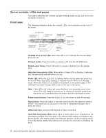
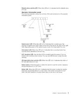
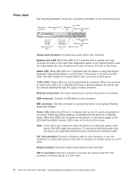
Rear view The following illustration shows the connectors and LEDs on the rear of the server. Power-cord connector System-error LED Link LEDs Select LED Ethernet 2 connector C2T IN connector IN Serial connector C2T OUT connector OUT Power LED USB 3 connector Ethernet 1 connector ISM connector Power-cord connector: Connect the power cord to this connector. System-error LED: When this LED is lit, it indicates that a system error has occurred. An LED on the Light Path Diagnostics panel on the system board is also lit to help isolate the error. A system-error LED is also on the front of the server. Select LED: When this LED is lit, it indicates that this server is using the monitor, keyboard, and pointing device in a C2T chain. If the server is not part of a C2T chain, this LED remains lit. A select LED is also on the front of the server. Tx/Rx LEDs: These LEDs are on the dual Ethernet connector. When the up-arrow or down-arrow LED is lit, it indicates that there is activity between the server and the network attached through the upper or lower connector. Ethernet connectors: Use these connectors to connect the server to a network. USB connector: Connect a USB device to this connector. ISM connector: Use this connector to connect the server to an optional Remote Supervisor Adapter. Power LED: When this LED is lit, it indicates that ac and dc power are present in the server. When this LED is flashing, it indicates that the server is in Standby mode. When this LED is off, ac power is not present, or the power supply or the LED itself has failed. A power LED is also on the front of the server. Note: If this LED is off, it does not mean that there is no electrical power in the server. The LED might be burned out. To remove all electrical power from the server, you must disconnect the power cord from the electrical outlet. C2T Out connector: Connect a breakout cable to this connector, or use this connector to connect the server to the C2T In connector of another server in a C2T chain. Serial connector: Connect a 9-pin serial device to this connector. C2T In connector: Use this connector to connect the server to the C2T Out connector of another server in a C2T chain. 6 xSeries 335 Type 8676, Type 8830: Hardware Maintenance Manual and Troubleshooting Guide
-
 1
1 -
2
-
3
-
4
-
5
-
6
-
7
-
8
-
9
-
10
-
 11
11 -
 12
12 -
 13
13 -
 14
14 -
 15
15 -
 16
16 -
 17
17 -
 18
18 -
 19
19 -
 20
20 -
 21
21 -
22
-
23
-
24
-
25
-
26
-
27
-
28
-
29
-
30
-
31
-
32
-
33
-
34
-
35
-
36
-
37
-
38
-
39
-
40
-
41
-
42
-
43
-
44
-
45
-
46
-
47
-
48
-
49
-
50
-
51
-
52
-
53
-
54
-
55
-
56
-
57
-
58
-
59
-
60
-
61
-
62
-
63
-
64
-
65
-
66
-
67
-
68
-
69
-
70
-
71
-
72
-
73
-
74
-
75
-
76
-
77
-
78
-
79
-
80
-
81
-
82
-
83
-
84
-
85
-
86
-
87
-
88
-
89
-
90
-
91
-
92
-
93
-
94
-
95
-
96
-
97
-
98
-
99
-
100
-
101
-
102
-
103
-
104
-
105
-
106
-
107
-
108
-
109
-
110
-
111
-
112
-
113
-
114
-
115
-
116
-
117
-
118
-
119
-
120
-
121
-
122
-
123
-
124
-
125
-
126
-
127
-
128
-
129
-
130
-
131
-
132
-
133
-
134
-
135
-
136
-
137
-
138
-
139
-
140
-
141
-
142
-
143
-
144
-
145
-
146
-
147
-
148
-
149
-
150
-
151
-
152
-
153
-
154
-
155
-
156
-
157
-
158
-
159
-
160
-
161
-
162
-
163
-
164
-
165
-
166
-
167
-
168
-
169
-
170
-
171
-
172
 |
 |
