IBM 8676 Hardware Maintenance Manual - Page 87
components
 |
UPC - 087944770107
View all IBM 8676 manuals
Add to My Manuals
Save this manual to your list of manuals |
Page 87 highlights
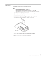
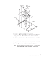
System board screws (7 places) Heat-sink retainer bracket screws (8 places) I/O port screws (6 places) Locator hole Locator pin 13. Remove the six I/O port screws at the rear of the server. 14. Remove the eight screws securing the two heat sink retention modules to the system board. These eight screws also secure the system board to the chassis. 15. Remove the seven screws on the system board that secure the system board to the chassis. 16. Pull the board carefully out of the server, taking special care not to disturb any surrounding components. 17. To reinstall the board, place it carefully into position and ensure the locator pin engages the locator hole in the system board. 18. Reverse steps 5 on page 76 through 12 on page 76 to replace the components that were removed. Note: When reassembling the components in the server, be sure to route all cables carefully so that they are not exposed to undue pressure. Chapter 5. Service replaceable units 77
-
 1
1 -
2
-
3
-
4
-
5
-
6
-
7
-
8
-
9
-
10
-
11
-
12
-
13
-
14
-
15
-
16
-
17
-
18
-
19
-
20
-
21
-
22
-
23
-
24
-
25
-
26
-
27
-
28
-
29
-
30
-
31
-
32
-
33
-
34
-
35
-
36
-
37
-
38
-
39
-
40
-
41
-
42
-
43
-
44
-
45
-
46
-
47
-
48
-
49
-
50
-
51
-
52
-
53
-
54
-
55
-
56
-
57
-
58
-
59
-
60
-
61
-
62
-
63
-
64
-
65
-
66
-
67
-
68
-
69
-
70
-
71
-
72
-
73
-
74
-
75
-
76
-
77
-
78
-
79
-
80
-
81
-
 82
82 -
 83
83 -
 84
84 -
 85
85 -
 86
86 -
 87
87 -
 88
88 -
 89
89 -
 90
90 -
 91
91 -
 92
92 -
93
-
94
-
95
-
96
-
97
-
98
-
99
-
100
-
101
-
102
-
103
-
104
-
105
-
106
-
107
-
108
-
109
-
110
-
111
-
112
-
113
-
114
-
115
-
116
-
117
-
118
-
119
-
120
-
121
-
122
-
123
-
124
-
125
-
126
-
127
-
128
-
129
-
130
-
131
-
132
-
133
-
134
-
135
-
136
-
137
-
138
-
139
-
140
-
141
-
142
-
143
-
144
-
145
-
146
-
147
-
148
-
149
-
150
-
151
-
152
-
153
-
154
-
155
-
156
-
157
-
158
-
159
-
160
-
161
-
162
-
163
-
164
-
165
-
166
-
167
-
168
-
169
-
170
-
171
-
172
 |
 |
