Icom IC-A110 Instruction Manual - Page 6
Function display
 |
View all Icom IC-A110 manuals
Add to My Manuals
Save this manual to your list of manuals |
Page 6 highlights
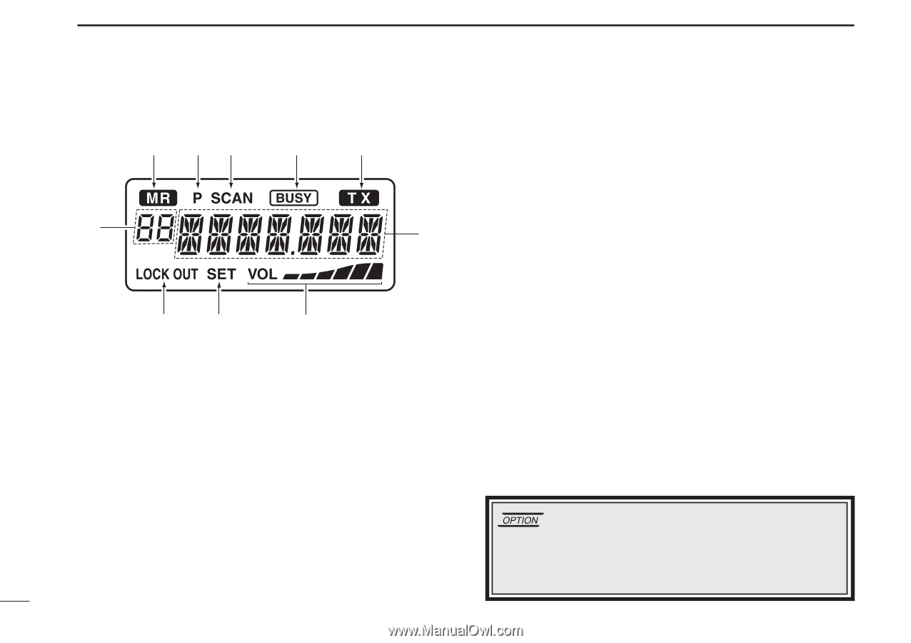
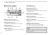
1 PANEL DESCRIPTION I Function display q we r !1 t y t TX INDICATOR (p. 5) Appears while transmitting. y FREQUENCY DISPLAY (p. 11) ➥Shows the operating frequency. ➥Shows the channel name when the memory name function is selected. (p. 10) u VOLUME LEVEL INDICATORS ➥ Shows the AF volume level(while receiving). o i u i SET MODE INDICATOR ➥ Appears when the Initial set mode is selected. (p. 12) q MEMORY MODE INDICATOR (p. 5) Appears when memory mode is selected. w DUALWATCH INDICATOR (p. 7) Indicates when the dualwatch function is activated. e SCAN INDICATOR (p. 8) Indicates when the scan function is selected. o LOCK OUT INDICATOR ➥ Appears when the channel is set as a 'LOCK OUT' chan- nel. (p. 8) !0 MEMORY CHANNEL INDICATOR ➥ Indicates the selected memory channel number ➥ 'Pr' appears when the priority channel is selected. r BUSY INDICATOR (p. 6) "BUSY" appears when receiving a signal or when the squelch is open. (p. 6) *NOTE: The VFO/memory switch [V/M] and the memory write switch [M/W] functions may not be available depending on version. 3
-
 1
1 -
 2
2 -
 3
3 -
 4
4 -
 5
5 -
 6
6 -
 7
7 -
 8
8 -
 9
9 -
 10
10 -
 11
11 -
 12
12 -
13
-
14
-
15
-
16
-
17
-
18
-
19
-
20
-
21
-
22
-
23
-
24
 |
 |