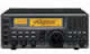
Icom IC-R8500 Instruction Manual - Page 12
Antenna connection, Grounding
 |
View all Icom IC-R8500 manuals
Add to My Manuals
Save this manual to your list of manuals |
Page 12 highlights
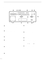
2 CONNECTIONS s Antenna connection Antennas play a very important role in receiver operation. Connecting a poor quality antenna to the IC-R8500 will result in less than optimum performance. The IC-R8500 requires at least 2 antennas for full frequency coverage: one for 0.1 to 30 MHz and one for 30 to 2000 MHz. D Using a long wire antenna for HF bands The IC-R8500 has a 500 Ω phono (RCA) antenna connector for the HF bands. When using a long wire antenna, instead of a 50 Ω matched antenna, use one as long as possible (at least 10 m, 33 ft) and select the active connector as follows: Œ Push [SLEEP/ SET ] for 1 sec. to enter quick set mode. Rotate the [M-CH] selector to select the "HF ANT" item. Ž Rotate the main dial to select the antenna connector. Push [SLEEP/ SET ] momentarily to exit quick set mode. 500 HF ANT s Grounding RWARNING: NEVER use a gas pipe or electri- cal conduit pipe for grounding. To prevent accidents involving electricity and interference from transceivers, ground the receiver through the [GND] terminal on the rear panel. For best results, connect a heavy gauge cable to a water pipe or long, earth-sunk copper rod. Make the distance between the [GND] terminal and ground as short as possible. TYPE-N CONNECTOR INSTALLATION EXAMPLE Œ Nut Rubber gasket 15 mm Clamp Washer 3 mm 6 mm Center conductor (10 mm ≈ 3⁄8 in) Slide the nut, washer, rubber gasket and clamp over the coaxial cable, then cut the end of the cable evenly. Strip the cable and fold the braid back over the clamp. Ž Solder hole Soft solder the center conductor. Install the center conductor pin and No space solder it. Plug body Carefully slide the plug body into place aligning the center conductor pin on the cable. Tighten the nut onto the plug body. • Be sure the center conductor is the same height as the plug body. PL-259 CONNECTOR INSTALLATION EXAMPLE Œ 30 mm Slide the coupling ring Ž down. Strip the cable Coupling ring jacket and soft solder. 10 mm (soft solder) solder solder Slide the connector body on and solder it. 10 mm Soft Strip the cable as solder shown at left. Soft solder the center con- 1-2 mm ductor. (10 mm ≈ 3⁄8 in) 9 Screw the coupling ring onto the connector body.
-
 1
1 -
2
-
3
-
4
-
5
-
6
-
 7
7 -
 8
8 -
 9
9 -
 10
10 -
 11
11 -
 12
12 -
 13
13 -
 14
14 -
 15
15 -
 16
16 -
 17
17 -
18
-
19
-
20
-
21
-
22
-
23
-
24
-
25
-
26
-
27
-
28
-
29
-
30
-
31
-
32
-
33
-
34
-
35
-
36
-
37
-
38
-
39
-
40
-
41
-
42
-
43
-
44
-
45
-
46
-
47
-
48
 |
 |
