Icom IC-R8500 Instruction Manual - Page 8
Rear panel - cable
 |
View all Icom IC-R8500 manuals
Add to My Manuals
Save this manual to your list of manuals |
Page 8 highlights
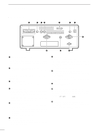
1 PANEL DESCRIPTION s Rear panel q w er t yu i !1 !0 o q RS-232C CONNECTOR (p. 10) Connects an RS-232C cable. An RS-232C cable can be used to connect the IC-R8500 to a PC. In this way commands can be sent to the receiver via the PC. w CI-V REMOTE CONTROL JACK (p. 10) Allows connection to an Icom CI-V system transceiver or another receiver for the transceive function. Also connects to a PC with several receivers for command control via an optional CT-17 CI-V LEVEL CONVERTER. e IF OUT JACK (p. 40) Outputs a 10.7 MHz IF signal with 9 V DC for an optional TV-R7100 TV RECEIVE ADAPTER. r AGC JACK (pgs. 16, 40) This jack has functions which are selectable through internal receiver settings. • Outputs an AGC signal for an optional TV-R7100 TV RECEIVE ADAPTER (default). • Outputs audio detected signal without de-emphasis for 9600 bps data detection (FM mode only). t DC 13.8 V JACK (p. 8) ¯ Plug in the jumper connector here when using the supplied* AC adapter. ¯ Connects to a 13.8 V DC power source using the supplied DC cable when the AC adapter is not connected. *Not supplied with some versions. y EXTERNAL SPEAKER JACK Connects an 8 Ω external speaker. • When an external speaker is connected, the internal speaker does not function. u DC IN JACK (p. 8) Connects the supplied* AC adapter. • A regulator circuit has been designed between this connector and the DC 13.8 V jack. • Be sure the jumper connector is connected to the DC 13.8 V jack. *Not supplied with some versions. i HF 50 Ω ANTENNA CONNECTOR (p. 8) Connects an antenna to cover the frequency range below 30 MHz. • Use a coaxial cable and a PL-259 connector. • Be sure this connector is selected in quick set mode (p. 31). o GROUND TERMINAL (p. 9) Connect this terminal to a ground. !0 HF 500 Ω ANTENNA CONNECTOR (p. 8) When a 500 Ω long wire antenna is used for HF band receiving, this connector is used instead of the 50 Ω antenna connector. • Set the "HF ANT" item to 500 to use this connector (p. 31). !1 VHF/UHF ANTENNA CONNECTOR (p. 8) Connects an antenna to cover the frequency range over 30 MHz. • Use a coaxial cable and type-N connector. 5
-
 1
1 -
2
-
 3
3 -
 4
4 -
 5
5 -
 6
6 -
 7
7 -
 8
8 -
 9
9 -
 10
10 -
 11
11 -
 12
12 -
 13
13 -
14
-
15
-
16
-
17
-
18
-
19
-
20
-
21
-
22
-
23
-
24
-
25
-
26
-
27
-
28
-
29
-
30
-
31
-
32
-
33
-
34
-
35
-
36
-
37
-
38
-
39
-
40
-
41
-
42
-
43
-
44
-
45
-
46
-
47
-
48
 |
 |
