Icom IC-R8500 Instruction Manual - Page 6
Delay/speed Control [delay/speed]
 |
View all Icom IC-R8500 manuals
Add to My Manuals
Save this manual to your list of manuals |
Page 6 highlights
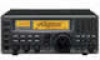
1 PANEL DESCRIPTION POWER SLEEP/ SET REC REMOTE REC OUT PHONES S 1 3 5 7 9 +20dB +60dB SIGNAL iC- r8500 COMMUNICATION RECEIVER FM SLEEP LOCK NB AFC AGC-F APF-N RECV 10-ATT-20 BANK ICOM WFM MODE FM AM SSB/CW NB/AFC AF GAIN AGC 10dB 20dB SQUELCH APC IF SHIFT TS TS SPCH LOCK APF @1 MEMORY SET SWITCH [M-SET] (p. 19) Used to 'copy and paste' the displayed frequency into another memory channel. • The first push is used to copy ( M appears), and the second push is used to paste ( M disappears). • Frequency, mode, tuning step, memory name, etc. can be programmed into a temporary memory. @2 MEMORY CLEAR SWITCH [M-CL] (p. 19) Push and hold to clear the contents of the displayed memory. • Bank names cannot be cleared. ing on the [DLY D/S ] switch setting. • When scan delay time is assigned, this control adjusts the scan delay time (scan pausing interval) during signal reception. This setting is effective when " " is selected for the scan resume condition. • When scan speed is assigned, this control adjusts the scan speed. In this case, scan delay time is determined while setting. @7 SCAN SWITCHES [SCAN SCAN SET ] All of these switches are related to the scan function in some way as follows: @3 MEMORY WRITE SWITCH [MW] (p. 19) Push and hold to store the displayed frequency, mode, tuning step, etc. into the selected memory channel. @4 BANK SWITCH [BANK] (p.17) ¯ Push momentarily to toggle the bank limit function ON and OFF (p 18). • While "BANK" appears, only memory channels within the selected bank can be selected via the [M-CH] selector. ¯ Push for 1 sec. to increase/decrease the number of memory channels in the selected bank (p. 21). @5 MEMORY CHANNEL SELECTOR [M-CH] (p.18) ¯ Selects a memory channel in normal use. • Clockwise rotation selects higher memory channel numbers; counterclockwise rotation selects lower memory channel numbers. ¯ Selects a set mode item when quick set mode or initial set mode is selected (p. 30). @6 DELAY/SPEED CONTROL [DELAY/SPEED] (p.28) Adjusts the scan delay time or scan speed depend- [MEMO] (p. 23) ¯ Push momentarily to start/stop memory scan. ¯ Push numeral keys, then this key to start memo- ry scan in the specified bank. ¯ Push this key, then a mode switch to activate mode select scan function. ¯ Push for 1 sec. to set automatic bank and skip functions. • The bank limit function and/or memory skip functions are activated automatically when "AUTO" is selected and scan is started. [SEL] (p. 23) ¯ Push momentarily to start/stop memory select scan. ¯ Push for 1 sec. to set the memory channel as a select channel. [PROG] (p. 24) ¯ Push momentarily to start/stop programmed scan. ¯ Push numeral keys, before or after pushing this key to start programmed scan using the specified scan edge group. • 10 scan edge groups are available. ¯ Push for 1 sec. to program scan edges for pro- 3
-
 1
1 -
 2
2 -
 3
3 -
 4
4 -
 5
5 -
 6
6 -
 7
7 -
 8
8 -
 9
9 -
 10
10 -
 11
11 -
 12
12 -
13
-
14
-
15
-
16
-
17
-
18
-
19
-
20
-
21
-
22
-
23
-
24
-
25
-
26
-
27
-
28
-
29
-
30
-
31
-
32
-
33
-
34
-
35
-
36
-
37
-
38
-
39
-
40
-
41
-
42
-
43
-
44
-
45
-
46
-
47
-
48
 |
 |
