Icom IC-R8500 Instruction Manual - Page 5
Audio Peak Filter Switch [apf]
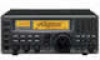 |
View all Icom IC-R8500 manuals
Add to My Manuals
Save this manual to your list of manuals |
Page 5 highlights
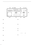
1 PANEL DESCRIPTION !9 ∞ OFF DLY kHz SEL-CH SKIP-CH IC-R8500 M 1 QZ 4 GHI 2 ABC 5 JKL 3 DEF 6 MNO . ; , M-CH BANK 7 PRS . 8 TUV 0 9 WXY CE NAME BANK ENT ENT MEMO SEL PROG AUTO SCAN/ SCAN SET SKIP VSC PRIO DLY D/S M-SET M-CH DELAY/SPEED BANK M-CL MW !5 !6 !7 !8 Center frequency is shifted down. Center frequency is shifted up. • Automatic announcement at signal detection during scan is available. Refer to the "REC SPCH" item on p. 31 for details. ¯ Push for 1 sec. to activate the lock function (p. 12). • Push for 1 sec. again to cancel the lock function. • The lock function action can be selected in set mode !2 AUDIO PEAK FILTER CONTROL [APF] (p. 15) Adjusts the audio peak filter setting to pick up a desired audio frequency. Only valid when the [APF] switch is ON. • Clockwise rotation adjusts the filter setting higher; coun- to cover the main dial only, or to cover both the main dial and front panel switches. !6 TUNING STEP SWITCHES [TSv]/[TSw] (p. 12) Select the tuning step for the main dial. Push [TSv] to select a larger tuning step; push [TSw] to select terclockwise rotation adjusts the filter setting lower. a smaller tuning step. !3 ATTENUATOR SWITCHES [10dB]/[20dB] Push to activate one of the attenuators. ± Push [10dB] to activate the 10 dB attenuator. ± Push [20dB] to activate the 20 dB attenuator. ± Push [10dB] + [20dB] to activate the 30 dB attenuator. • 10 dB and 30 dB attenuator cannot be used below 500 kHz. • 10 Hz, 50 Hz, 100 Hz, 1 kHz, 2.5 kHz, 5 kHz, 9 kHz, 10 kHz, 12.5 kHz, 20 kHz, 25 kHz, 100 kHz and 1 MHz are selectable. • Programmable tuning steps can be set between 0.5 and 199.5 kHz. « To set programmable tuning steps, enter the desired steps via the keypad, then push [TSY]or [TSZ]. !4 AUDIO PEAK FILTER SWITCH [APF] (p. 15) ¯ Push momentarily to toggle the audio peak filter circuit ON and OFF. • Use the [APF] control to adjust the center of the audio !7 MAIN DIAL Changes the operating frequency, set mode contents, etc. peak passband. ¯ When the audio peak filter circuit is ON, push for 1 sec. to toggle the filter setting between normal !8 BRAKE ADJUSTMENT SCREW Adjusts the main dial tension. and narrow. • 'Narrow' is available for SSB, CW and AM only. !9 FUNCTION DISPLAY (p. 6) Shows the selected frequency, mode, memory !5 SPEECH/LOCK SWITCH [SPCH/LOCK] name, etc. ¯ Push momentarily to activate the voice synthesizer function and have the displayed frequency announced. • An optional UT-102 SPEECH SYNTHESIZER UNIT is necessary to activate the voice synthesizer function (p. 38). @0 S-METER ¯ Shows the strength of the received signal. ¯ Shows the squelch threshold level when the [SQUELCH] is rotated past the center position. 2
-
 1
1 -
 2
2 -
 3
3 -
 4
4 -
 5
5 -
 6
6 -
 7
7 -
 8
8 -
 9
9 -
 10
10 -
 11
11 -
12
-
13
-
14
-
15
-
16
-
17
-
18
-
19
-
20
-
21
-
22
-
23
-
24
-
25
-
26
-
27
-
28
-
29
-
30
-
31
-
32
-
33
-
34
-
35
-
36
-
37
-
38
-
39
-
40
-
41
-
42
-
43
-
44
-
45
-
46
-
47
-
48
 |
 |
