Intel 945G User Manual - Page 24
Setting up the Evaluation Board - motherboard
 |
UPC - 735858177825
View all Intel 945G manuals
Add to My Manuals
Save this manual to your list of manuals |
Page 24 highlights
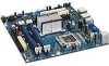
Intel® 945G Express Chipset Development Kit User's Manual Setting Up the Development Kit Power Supply The evaluation board requires the use of a standard desktop ATX power supply with a minimum of 250 W output. The power supply selected must also provide an auxiliary 2x2 12 V connector. Other Devices and Adapters The evaluation board functions much like a standard desktop computer motherboard. Most PC-compatible peripherals can be attached and configured to work with the board. 3.3 Setting up the Evaluation Board Once the hardware described in the previous section is gathered, follow the steps below to set up the evaluation board. This manual assumes you are familiar with the basic concepts involved in installing and configuring PC hardware. Note: To locate items discussed in the procedure below, please refer to Chapter 4. 1. Create a safe work environment. Make sure you are in a static-free environment before removing any components from their anti-static packaging. The evaluation board is susceptible to electrostatic discharge damage, and such damage may cause product failure or unpredictable operation. 2. Inspect the contents of your kit. Check for damage that may have occurred during shipment. Contact your sales representative if any items are missing or damaged. Caution: Connecting the wrong cable or reversing the cable can damage the evaluation board and may damage the device being connected. Since the board is not in a protective chassis, use caution when connecting cables to this product. Caution: Do not connect the power supply to the board until all other steps have been completed. The last step in the installation process must be to plug the AC cord to the power supply. Standby voltage is constantly applied to the board. Therefore, do not insert or remove any hardware unless the system is unplugged. Note: The evaluation board is a microATX form factor. An ATX chassis may be used if a protected environment is desired. 3. Check the jumper settings (refer to Section 4.3.1). Jumper J6J3 is used to clear the CMOS memory. Make sure this jumper is set for normal operation. 4. Populate hardware component to the evaluation board. Make sure the following hardware is populated on your evaluation board. Please refer to Section 3.3.1 for more detail on the memory configurations. a. 1x 3.4 GHz Intel® Pentium® 4 Processor 551 b. 1x CPU thermal solution c. At least one 256 MByte DDR2 533 DIMM or 1x 256 MByte DDR2 400 DIMM 5. Install CPU fan heat sink. 6. Install a SATA or IDE hard disk drive. 7. Connect any additional storage devices to the evaluation board. 8. Connect a floppy drive (optional). 24 Reference #308823
-
 1
1 -
2
-
3
-
4
-
5
-
6
-
7
-
8
-
9
-
10
-
11
-
12
-
13
-
14
-
15
-
16
-
17
-
18
-
 19
19 -
 20
20 -
 21
21 -
 22
22 -
 23
23 -
 24
24 -
 25
25 -
 26
26 -
 27
27 -
 28
28 -
 29
29 -
30
-
31
-
32
-
33
-
34
-
35
-
36
-
37
-
38
-
39
-
40
-
41
-
42
-
43
-
44
-
45
-
46
-
47
-
48
-
49
-
50
-
51
-
52
-
53
-
54
 |
 |
