Intel 945G User Manual - Page 41
Primary Features
 |
UPC - 735858177825
View all Intel 945G manuals
Add to My Manuals
Save this manual to your list of manuals |
Page 41 highlights
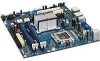
Intel® 945G Express Chipset Development Kit User's Manual Hardware References 4.1.2 Figure 12 Back Panel Connectors The illustration below shows the location of the back panel connectors for boards equipped with the 8-channel (7.1) audio subsystem. The back panel connectors are color-coded. The figure legend (Table 14) lists the colors used (when applicable). Back Panel I/O Connectors Table 14 Back Panel I/O Connectors Item/Callout from Figure 12 A B C D E F G H I J K M N O P Description PS/2 mouse port [green] PS/2 keyboard port [purple] S/PDIF digital audio output S/PDIF digital audio input Parallel port [burgundy] VGA port 4x USB port RJ45 LAN connector 2x USB port Surround L/R audio port Surround rear L/R audio port Center audio port MIC in Line in Front / line out 4.2 Primary Features This section will discuss the reference designator for the core component, expansion slots, processor socket, and PCI Express connector. Table 15 and 16 on the next page list the major board components. Reference #308823 41
-
 1
1 -
2
-
3
-
4
-
5
-
6
-
7
-
8
-
9
-
10
-
11
-
12
-
13
-
14
-
15
-
16
-
17
-
18
-
19
-
20
-
21
-
22
-
23
-
24
-
25
-
26
-
27
-
28
-
29
-
30
-
31
-
32
-
33
-
34
-
35
-
 36
36 -
 37
37 -
 38
38 -
 39
39 -
 40
40 -
 41
41 -
 42
42 -
 43
43 -
 44
44 -
 45
45 -
 46
46 -
47
-
48
-
49
-
50
-
51
-
52
-
53
-
54
 |
 |
