Intel 945G User Manual - Page 39
Board Layout
 |
UPC - 735858177825
View all Intel 945G manuals
Add to My Manuals
Save this manual to your list of manuals |
Page 39 highlights
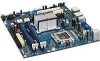
Intel® 945G Express Chipset Development Kit User's Manual Hardware References 4.1.1 Figure 11 Board Layout Figure 11 shows the location of the major components. Evaluation Board Major Components Table 13 The table below describes the lists of components identified above. Evaluation Board Components Item / Callout from Figure 11 A B C D E F Description Audio codec Front panel audio connector Ethernet device PCI Conventional bus add-in card connectors [2] PCI Express x16 bus add-in card connector Back panel connectors Reference #308823 39
-
 1
1 -
2
-
3
-
4
-
5
-
6
-
7
-
8
-
9
-
10
-
11
-
12
-
13
-
14
-
15
-
16
-
17
-
18
-
19
-
20
-
21
-
22
-
23
-
24
-
25
-
26
-
27
-
28
-
29
-
30
-
31
-
32
-
33
-
 34
34 -
 35
35 -
 36
36 -
 37
37 -
 38
38 -
 39
39 -
 40
40 -
 41
41 -
 42
42 -
 43
43 -
 44
44 -
45
-
46
-
47
-
48
-
49
-
50
-
51
-
52
-
53
-
54
 |
 |

Intel
®
945G Express Chipset Development Kit User’s Manual
Hardware References
Reference #308823
39
4.1.1
Board Layout
Figure 11 shows the location of the major components.
Figure 11
Evaluation Board Major Components
The table below describes the lists of components identified above.
Table 13
Evaluation Board Components
Item / Callout
from Figure 11
Description
A
Audio codec
B
Front panel audio connector
C
Ethernet device
D
PCI Conventional bus add-in card connectors [2]
E
PCI Express x16 bus add-in card connector
F
Back panel connectors