Intel 945G User Manual - Page 6
About This Manual - bios
 |
UPC - 735858177825
View all Intel 945G manuals
Add to My Manuals
Save this manual to your list of manuals |
Page 6 highlights
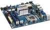
Intel® 945G Express Chipset Development Kit User's Manual About This Manual 1 About This Manual This user's manual describes the use of the Intel® 945G® Express Chipset Development Kit. This manual has been written for OEMs, system evaluators, and embedded system developers. All jumpers, headers, LED functions, and their locations on the board, along with subsystem features and POST codes, are defined in this document. For the latest information about the Intel® 945G® Express Chipset Development Kit reference platform, visit: http://developer.intel.com/design/intarch/devkits/index.htm For design documents related to this platform, such as schematics and bill of materials, please contact your Intel field sales representative. 1.1 Content Overview Chapter 1: About This Manual Description of conventions used in this manual. The last few sections explain how to obtain literature and contact customer support. Chapter 2: Development Kit Features Describes development kit features and board capability. This includes the information on the processor features, component features and operation, and overall development kit board capability. Chapter 3: Setting Up the Development Kit Board Complete instructions on how to configure the evaluation board and processor assembly by setting jumpers, connecting peripherals, providing power, and configuring the BIOS. Chapter 4: Hardware Reference Description of jumper settings and functions, board debug capabilities, and pinout information for connectors. 1.2 Text Conventions The following notations may be used throughout this manual. # The pound symbol (#) appended to a signal name indicates that the signal is active low. Variables Variables are shown in italics. Variables must be replaced with correct values. Instructions Instruction mnemonics are shown in uppercase. When you are programming, instructions are not case sensitive. You may use either upper case or lower case. Numbers Hexadecimal numbers are represented by a string of hexadecimal digits followed by the character H. A zero prefix is added to numbers that begin with A through F (e.g., FF is shown as 0FFH). Decimal and binary numbers are represented by their customary notations. (That is, 255 is a decimal number and 1111 1111 is a binary number. In some cases, the letter B is added for clarity.) 6 Reference #308823
-
 1
1 -
 2
2 -
 3
3 -
 4
4 -
 5
5 -
 6
6 -
 7
7 -
 8
8 -
 9
9 -
 10
10 -
 11
11 -
 12
12 -
13
-
14
-
15
-
16
-
17
-
18
-
19
-
20
-
21
-
22
-
23
-
24
-
25
-
26
-
27
-
28
-
29
-
30
-
31
-
32
-
33
-
34
-
35
-
36
-
37
-
38
-
39
-
40
-
41
-
42
-
43
-
44
-
45
-
46
-
47
-
48
-
49
-
50
-
51
-
52
-
53
-
54
 |
 |
