Contents
vii
4
Error Messages and Beep Codes
4.1
BIOS Error Messages
..................................................................................................
75
4.2
Port 80h POST Codes
.................................................................................................
77
4.3
Bus Initialization Checkpoints
......................................................................................
81
4.4
Speaker
.......................................................................................................................
82
4.5
BIOS Beep Codes
........................................................................................................
82
Figures
1.
Desktop Board D845GVFN Components
....................................................................
12
2.
Block Diagram
..............................................................................................................
13
3.
Location of the Standby Power Indicator LED on the D845GVFN Board
....................
38
4.
Back Panel Connectors
................................................................................................
46
5.
Audio, Power, and Hardware Control Connectors
.......................................................
48
6.
Add-in Board and Peripheral Interface Connectors
.....................................................
51
7.
External I/O Connectors
...............................................................................................
52
8.
Connection Diagram for Front Panel Connector
..........................................................
53
9.
Connection Diagram for Front Panel USB Connector
..................................................
55
10.
Location of the Jumper Blocks
.....................................................................................
56
11.
Desktop Board Dimensions
..........................................................................................
58
12.
I/O Shield Dimensions
..................................................................................................
59
13.
Localized High Temperature Zones
.............................................................................
62
Tables
1.
Feature Summary
........................................................................................................
10
2.
Manufacturing Options
.................................................................................................
11
3.
Specifications
...............................................................................................................
15
4.
Supported System Bus Frequency and Memory Speed Combinations
.......................
19
5.
Supported DDR DIMM Configurations
.........................................................................
20
6.
Direct Draw Supported Modes
.....................................................................................
22
7.
Video BIOS Video Modes Supported for Analog CRTs
...............................................
23
8.
Supported Configuration Modes
..................................................................................
24
9.
Details of bpp Configuration Modes
.............................................................................
25
10.
LAN Connector LED States
.........................................................................................
31
11.
Effects of Pressing the Power Switch
..........................................................................
33
12.
Power States and Targeted System Power
.................................................................
34
13.
Wake-up Devices and Events
......................................................................................
34
14.
Fan Connector Function/Operation
..............................................................................
36
15.
System Memory Map
...................................................................................................
39
16.
I/O Map
........................................................................................................................
40
17.
DMA Channels
.............................................................................................................
41
18.
PCI Configuration Space Map
......................................................................................
41
19.
Interrupts
......................................................................................................................
42
20.
PCI Interrupt Routing Map
...........................................................................................
44
21.
Front Panel Audio Connector
.......................................................................................
49
22.
Auxiliary Line In Connector (Optional)
.........................................................................
49
23.
ATAPI CD-ROM Connector (Optional)
.........................................................................
49
24.
ATX12V Power Connector
...........................................................................................
49
25.
Rear Chassis Fan Connector
.......................................................................................
50

 1
1 2
2 3
3 4
4 5
5 6
6 7
7 8
8 9
9 10
10 11
11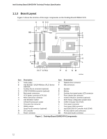 12
12

