Intel D845HV Intel Desktop Board D845HV Specification Update - Page 24
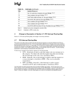
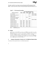
Change to Description of CD-ROM and Network Boot, Table 17., PCI Interrupt Routing Map
 |
View all Intel D845HV manuals
Add to My Manuals
Save this manual to your list of manuals |
Page 24 highlights
Intel Desktop Board D845HV Specification Update For example, using Table 17 as a reference, assume an add-in card using INTA is plugged into PCI bus connector 4. In PCI bus connector 4, INTA is connected to PIRQB, which is already connected to the SMBus. The add-in card in PCI bus connector 4 now shares interrupts with these onboard interrupt sources. Table 17. PCI Interrupt Routing Map Intel® ICH2 PIRQ Signal Name PCI Interrupt Source PIRQF PIRQG PIRQH PIRQB Other AGP connector Intel ICH2 USB controller #1 SMBus controller Intel ICH2 USB controller #2 INTB INTB INTC INTA to PIRQA INTD to PIRQD Intel ICH2 Audio / Modem Intel ICH2 LAN PCI Bus Connector 1 PCI Bus Connector 2 INTA INTB INTD INTA INTB INTC INTD INTB INTC INTA to PIRQE PCI Bus Connector 3 PCI Bus Connector 4 (Note) PCI Bus Connector 5 (Note) PCI Bus Connector 6 (Note) INTC INTB INTA INTB INTD INTC INTB INTC INTA INTD INTC INTD INTB INTA INTD INTA Note: D845WN board only. ✏ NOTE In PIC mode, the Intel ICH2 can connect each PIRQ line internally to one of the IRQ signals (3, 4, 5, 6, 7, 9, 10, 11, 12,14, and 15). Typically, a device that does not share a PIRQ line will have a unique interrupt. However, in certain interrupt-constrained situations, it is possible for two or more of the PIRQ lines to be connected to the same IRQ signal. In APIC mode, the allocation of PIRQ lines to IRQ signals is as shown in Table 17. 3. Change to Description of Section 3.8.1, CD-ROM and Network Boot The following note will be added to Section 3.8.1, CD-ROM and Network Boot: 18
-
 1
1 -
2
-
3
-
4
-
5
-
6
-
7
-
8
-
9
-
10
-
11
-
12
-
13
-
14
-
15
-
16
-
17
-
18
-
 19
19 -
 20
20 -
 21
21 -
 22
22 -
 23
23 -
 24
24 -
 25
25 -
 26
26 -
 27
27 -
 28
28 -
 29
29
 |
 |